Background Information #
For robot bin picking application, robot will pick items based on the relative position between vision base and taught pick point.
However, for user doesn’t care about the orientation of Rz when picking (for example: symmetric item or item placing could be random), the rotation of joint 6 will be a waste of cycle time.
By using 2.5D Component, user could optimize cycle time by reducing the unnecessary rotation for specific Rz, or even RX, Ry.
Brief Introduction #
2.5D Component is a point calculation component, which doesn’t include movement or I/O instruction. This gives user the freedom to adjust Point setting, control gripper IO, and check gripper sensor IO at the moment they want.
Component Explanation #
Points #
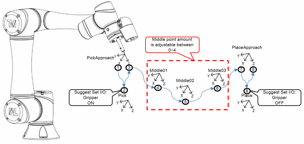
There are eight Points generated while 2.5D Component being used in project. The points are: Pick, PickApproach, Place, PlaceApproach, Middle01, Middle02, Middle03, Middle04. The explanation of those Points usage sequence is as below.
Adjustable Variables in Component #
There are six variables that could be adjusted in this Component, and detail explanation is as below table.
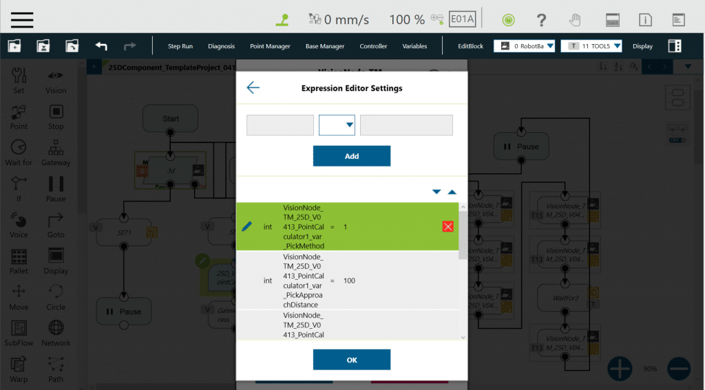
| Int_PickMethod | =1: robot will go to Pick point as user taught. =2: robot will go to Pick point as user taught, but Rz will follow the value while Pick was taught initially. =3: robot will go to Pick point as user taught, but Rx, Ry and Rz will follow the value while Pick was taught initially. 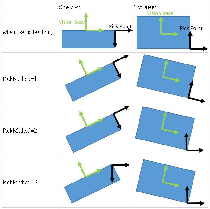 |
| Int_PickApproachDistance | The Z direction distance from Pick point to Pick_Approach point. |
| Bool_Middle_InterpointFromPickToPlace | =false: robot go to middle point as user taught. =true: robot go to middle point as user taught in X, Y and Z position, but Rx, Ry and Rz will be calculated by interpoint method. This will make robot rotate equally by each middle point through out the path from pick to place. 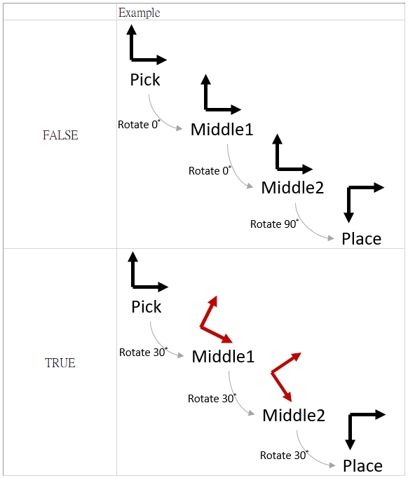 |
| Bool_PlaceCompensateOrNot | =false: robot will go to Place point as user taught regardless the picking method. =true: robot will compensate the rotation which adjusted by pick method, and place item with the angle you always wanted the item to be. 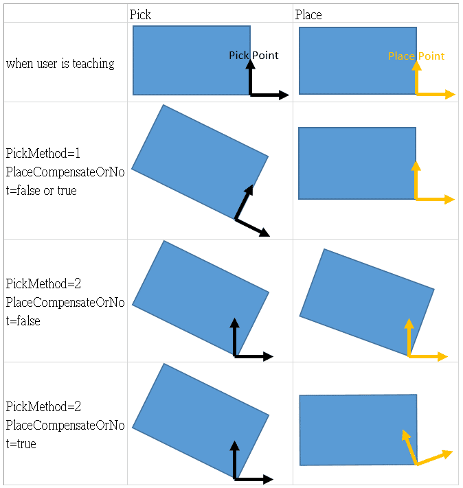 |
| Int_PlaceApproachDistance | The Z direction distance from Place point to Place_Approach point. |
| Int_MiddlePointAmount | =0~4. The amount of middle point needed between pick and place. |
Tool TCP #
Be noted all Points are based on a tool called VisionNode_TM_Tool, which will be included while Component is imported; so please adjust the TCP value of VisionNode_TM_Tool based on your case before teaching Points.
Global variable #
There are two global variables will be included while Component is imported: g_VisionNode_TM_VisionBase_Initial and g_VisionNode_TM_VisionBase_Current. Definition is defined as below table.
| g_VisionNode_TM_VisionBase_Initial | This g_var is intended to be used to save vision base value of the first time user trigger vision job before teaching the Pick point. |
| g_VisionNode_TM_VisionBase_Current | This g_var is intended to be used to save vision base value every time vision job executed while project is cycle running. |
Demo Program #
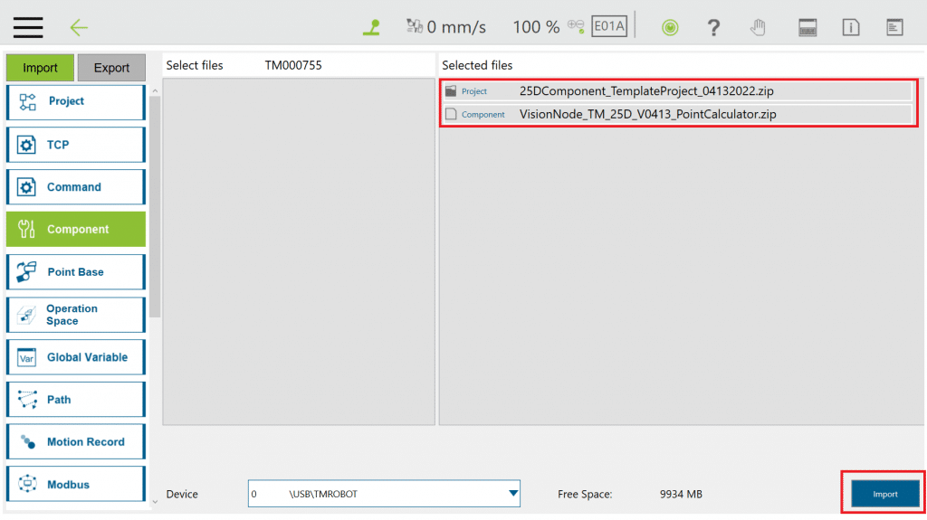
1. Import 2.5D component (necessary TCP and g_variables will be import together with Component, no need to import separately) and Template Project (Download here)
Navigate to ≡ > System > Import/Export> Select the project and component that you wanted, and press Import.
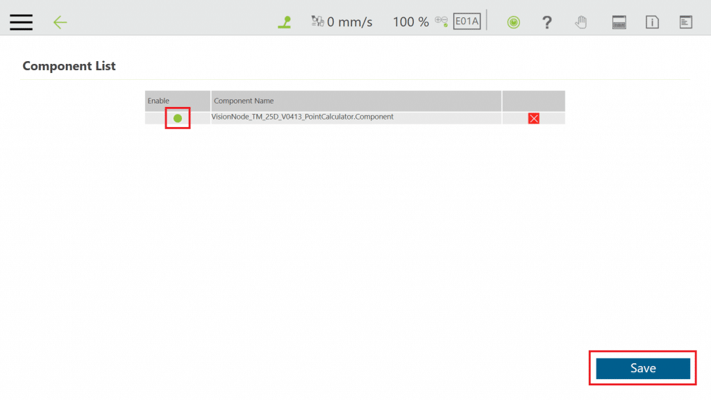
2. Enable the Component
Navigating to ≡ > Setting > Component> Check the radio button in front of the component, and press Save.
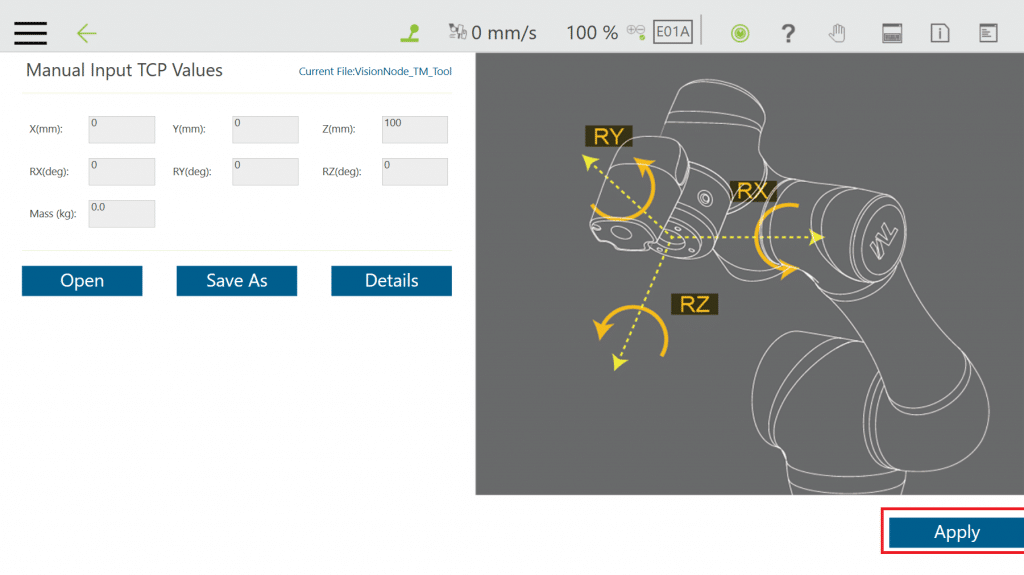
3. Adjust TCP: VisionNode_TM_Tool parameters to fit the tool you are using.
Navigating to ≡ >Setting > TCP> Input correct value for TCP (initial coordinate setting is {0,0,100,0,0,0}, mass is 0), and press Apply.
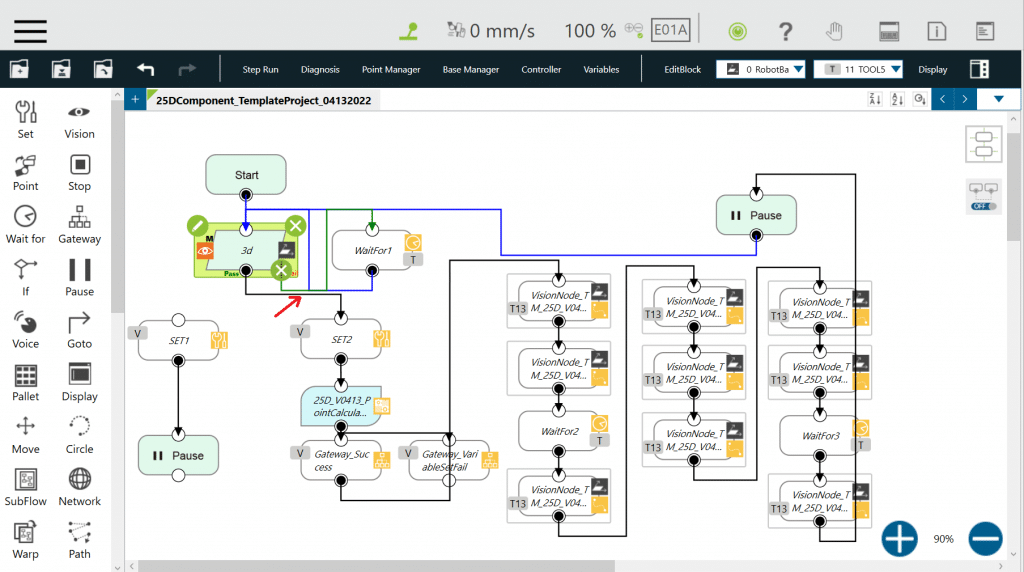
4. Open Template project
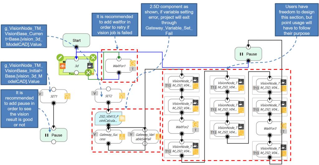
5. For the first time of project execution, please connect Vision Node with Set Node on the left, and execute once after 3D Vision Job is edited. During the execution, please make sure there is only one item on FOV, and check vision result is ideal or not.
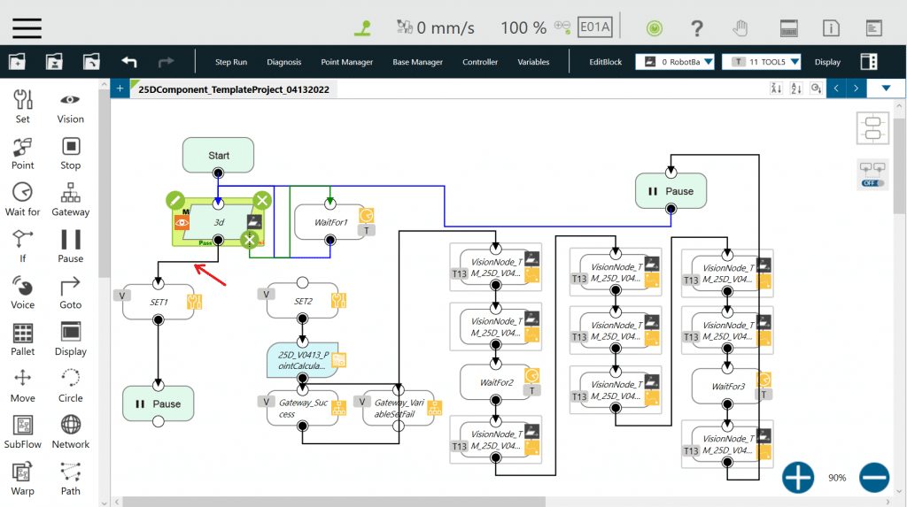
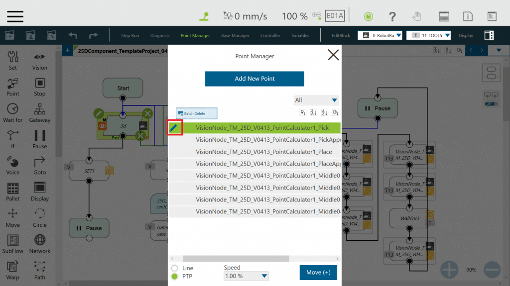
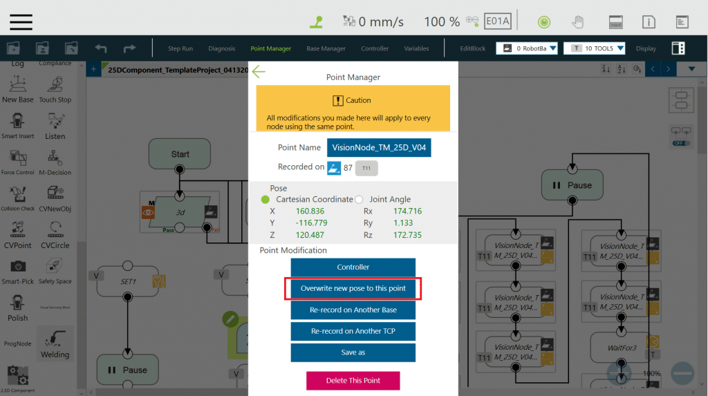
6. After first project execution, vision base will be saved into global variable: g_VisionNode_TM_VisionBase_Initial. Now user starts teaching following points inside Point Manager: Pick, Place, Middle(Middle point amount taught based on need, at most 4 middle point). Please drag robot to ideal position, press pencil icon beside point, then press Overwrite new pose to this point. PickApproach and PlaceApproach are no need to be taught since they will be calculated based on user’s setting.
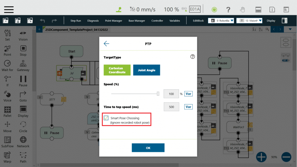
Please make sure Point Nodes are set as Smart Pose Choosing to avoid irrelevant rotation
7. Add Set Node to appropriate position based on your need to control gripper grip and release.
8. Edit variable inside 2.5D Component based on your preference.
9. After all setting complete, connect Vision Node with Set Node on the right, and project is ready for execution.
10. If user finds that the picking point is not desired, please redo Step 5 (Check on vision result is ideal or not) then teach Pick Point again.


