- Description of Control Box Inspection
- Introduction to the inspection scenario
- Configuration of TM Image Manager
- TMflow Edit and Configuration
- Scenario 1: Inspect Control Box and Transmit Image & Result to IM
- Scenario 2: Inspect Control Box and Review the Result
- Scenario 2: Inspect Control Box and Review the Result
- Configuration of Inspection Order NO. and SerialNo
- Version of TMflow Software: Detailed Information could be checked on Image Manager Manual, version used in this article is 2.14.6100
- Version of TMrobot Hardware : Detailed Information could be checked on Image Manager Manual, version used in this article is HW3.2
- Version of Image Manager on Server: Detailed Information could be checked on Image Manager Manual, version used in this article is 2.13.1400
- Version of Image Manager TMCraft/Service on Device: 2.14_v1_1 ,which could be downloaded from download center
- Requirements for other Hardware and Software
- A Control Box used for being inspected
- Polarizer
- Please note that there may be difference in the interface and steps between the old and new versions.
Description of Control Box Inspection #
Inspection procedures:
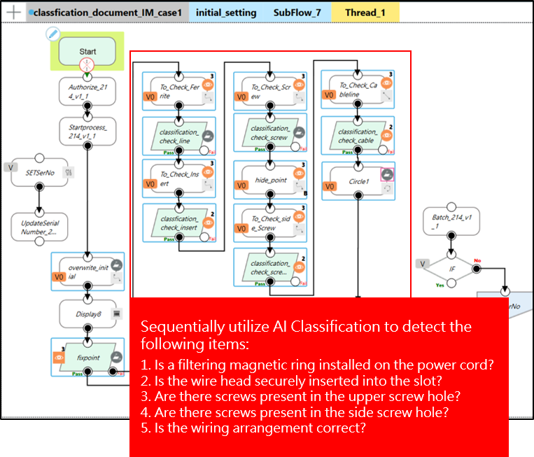
- Utilizing the display panel on the electronic control box, execute pattern matching for precise positioning and proceed to maneuver the Cobot to the designated inspection area. Employing AI Classification, systematically scrutinize the following elements:
- Verify the presence of a filtering magnetic ring on the power cord.
- Ensure insertion of the cable head into the slot.
- Confirm the presence of screws in the upper screw holes.
- Confirm the presence of screws in the side screw holes.
- Validate the correct arrangement of the wiring.
- Collaborate with TM Image Manager for image transmission and management
- For detailed AI Classification results and explanations, refer to the technical documentation
-
- TM AI+Classification application example – IPC inspection
Introduction to the inspection scenario #
Scenario 1 :
- Sequentially inspect the control box, transmitting the original images of each inspection item along with the corresponding inspection results to the TM Image Manager.
Scenario 2:
- Conduct sequential inspections on the control box and utilize the Image Manager Node with decision variables setting to transmit the inspection results to the TM Image Manager for further review.
- The inspection quantity is set to 2, with five inspection areas on the same control box undergoing 2 rounds of inspections. This setup simulates two control boxes that need to be inspected on a single production line.
- Additionally, incorporate a page for layout, allowing users to set reference samples for the purpose of conducting further review.
Configuration of TM Image Manager #
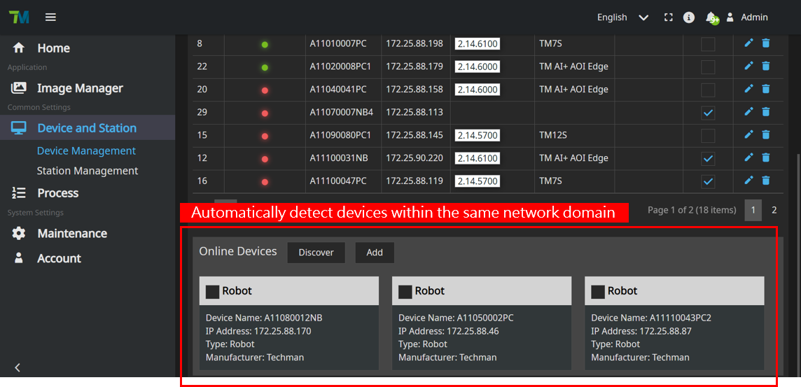
Within the Device and Station, select Device Management. There are two ways to add devices. First, utilize the automatic detection feature to add devices within the same network domain. The system will scan and identify the available devices for you to select and add. Second, Click on “Create” to manually add devices.
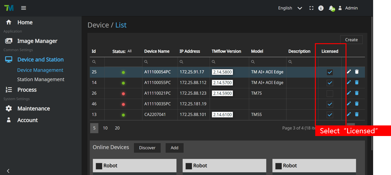
Select “Create” and manually input the designated name and IP address of the device. Subsequently, you can view the assigned robot name on the TMflow Login page.

Once the device is located, select “Licensed”
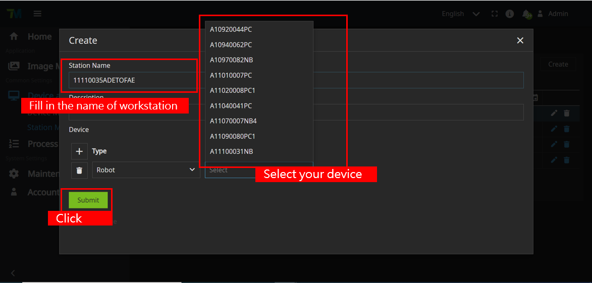
Select “Station Management” and click on “Create” to establish a workstation.
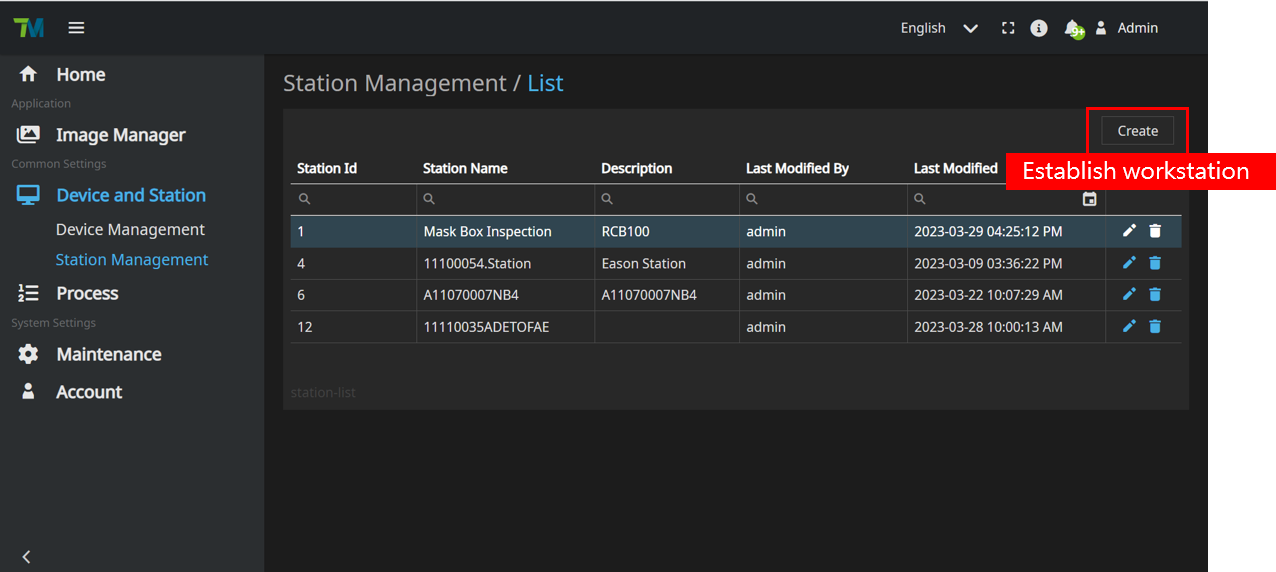
Fill in the name of the workstation and select the name of the device. Finally, click on “Submit”
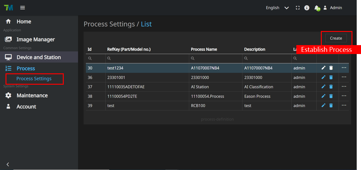
Select “Process Settings” within the “Process” and click on “Create” to establish the process.
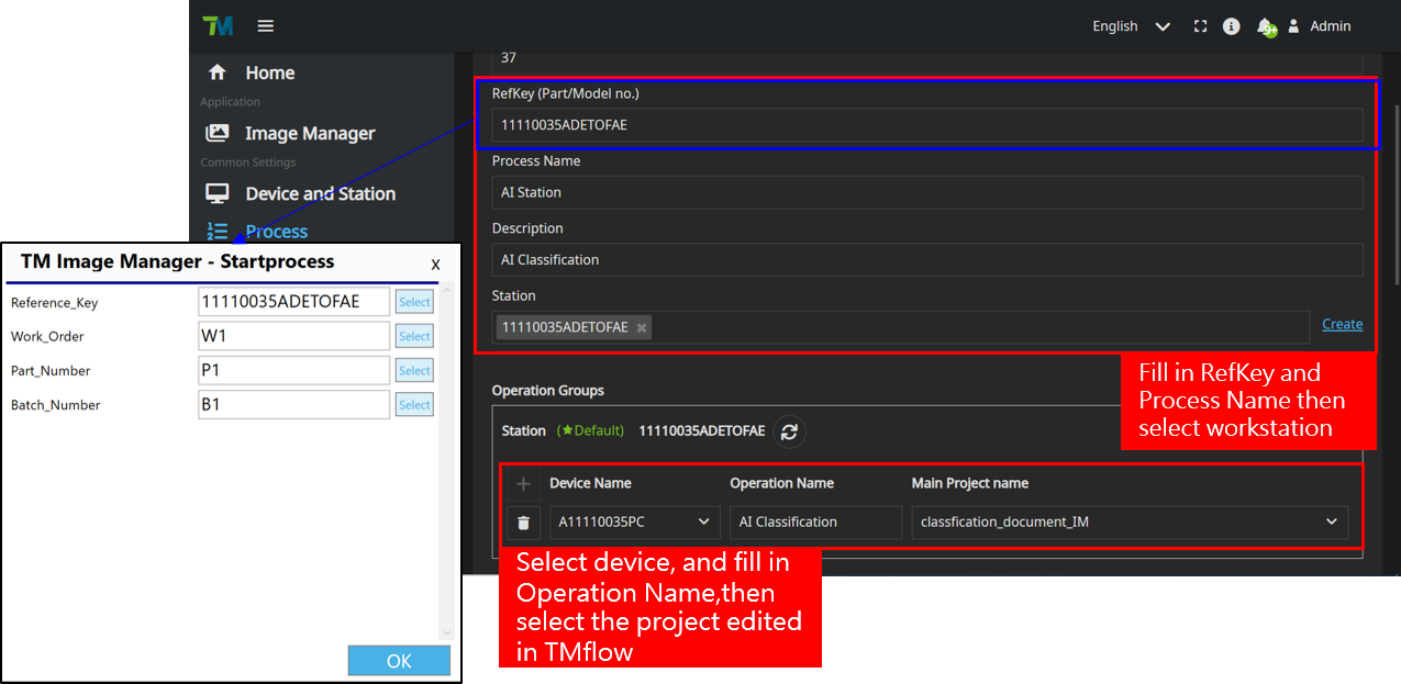
Fill in the relevant information within the Process, and in the workstation, select the device and the project edited in TMflow. Ensure that the Reference_Key corresponds to the configuration of the TMcraft Startprocess node.
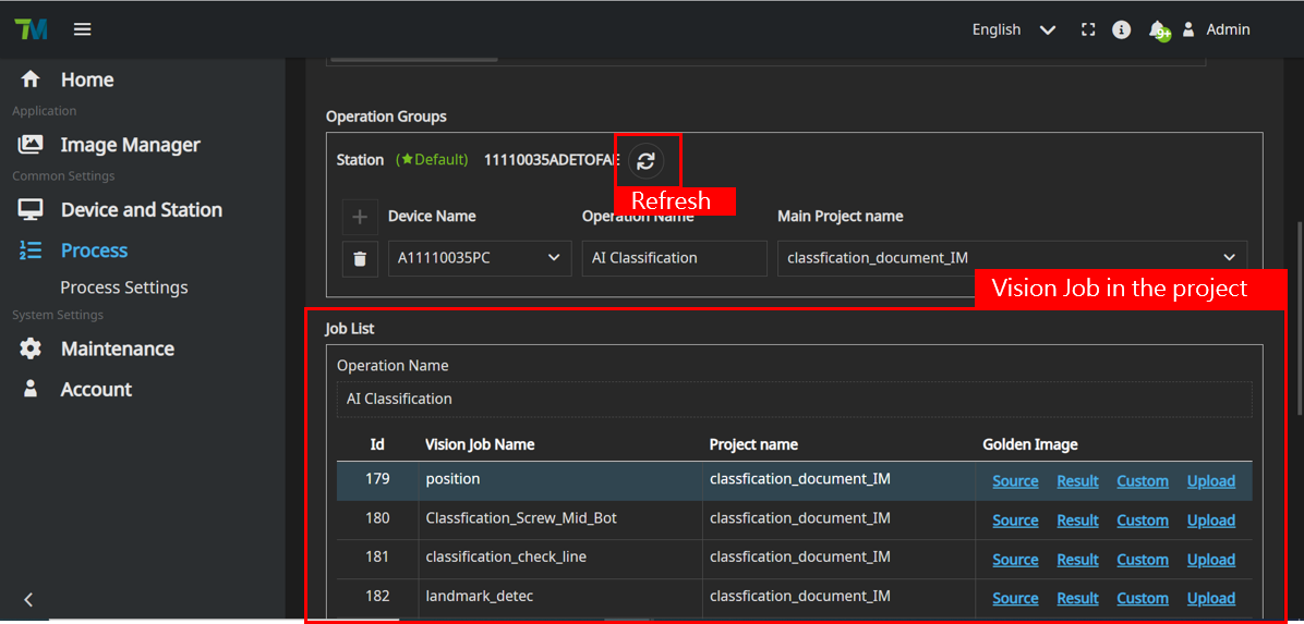
Upon establishing a successful connection, click on “Refresh” to view the Vision Job within the project
TMflow Edit and Configuration #
Import TMcraft Node/Service to TMFlow
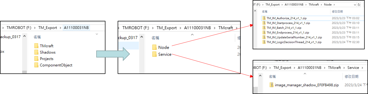
Place the designated file into the specified folder within the Techman SSD or a USB storage device named “TMROBOT”
- TM_Export/[your_computer]/ TMcraft/Node : TM_IM_[Authorize, Startprocess, Batch, Endprocess, UpdateSerialNumber].zip
- TM_Export/[your_computer]/ TMcraft/Service : image_manager_shadow_[checksum].zip
- If the “TMcraft/Node” and “TMcraft/Service” folders do not exist, you will need to create them manually.
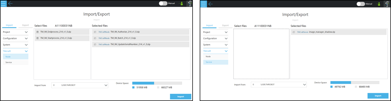
Import TMcraft Node/Service to TMFlow
TMflow->System->Import/Export: Select TMcraft
- Select Node: TM_IM_[Authorize, Startprocess, Batch, Endprocess, UpdateSerialNumber].zip
- Select Service: image_manager_shadow[checksum].zip
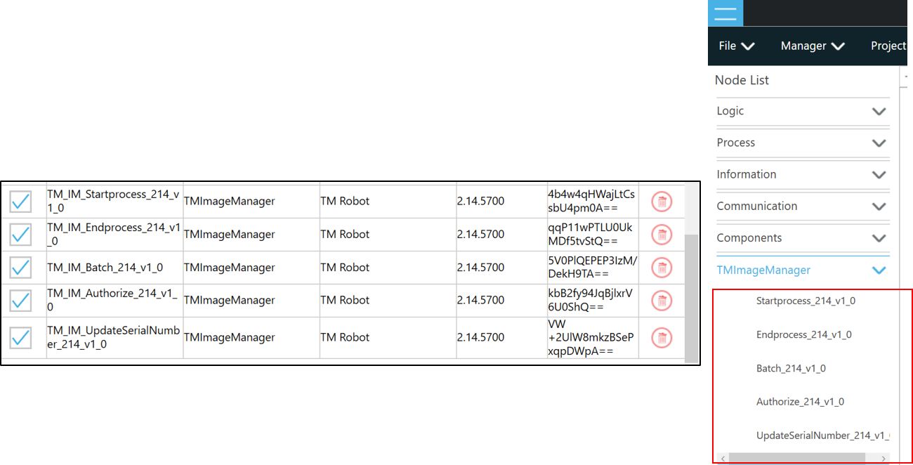
Enable TMcraft Node
TMflow->Configure->TMcraft Management : Select Node
- Enable all nodes and select save
- Check whether the nodes is existing in TMflow
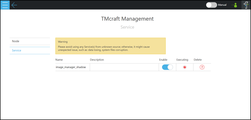
Enable TMcraft Service
TMflow->Configure->TMcraft Management : Select Service
- Enable image_manager_shadow.exe and restart TMflow
- Upon restarting TMflow,check whether the Executing turns from red into green
Scenario 1: Inspect Control Box and Transmit Image & Result to IM #
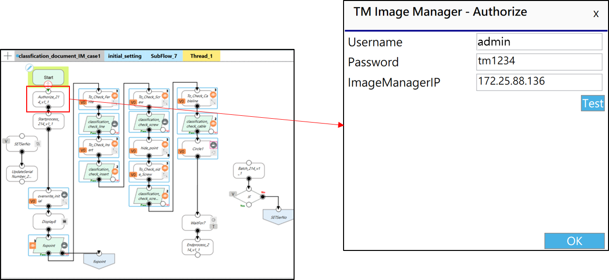
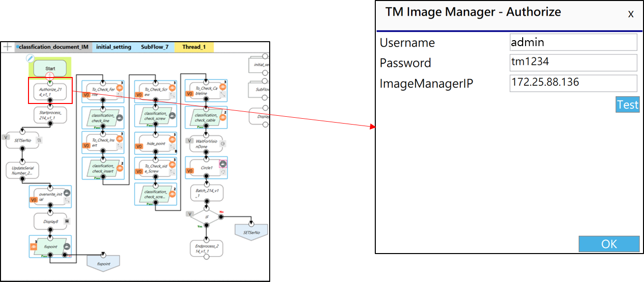
Authorize node
Edit Image Manager Node and Authorize node,
- Fill in the information
- Click“OK”
- Click“Test”to test the connection
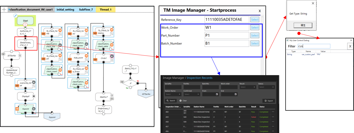
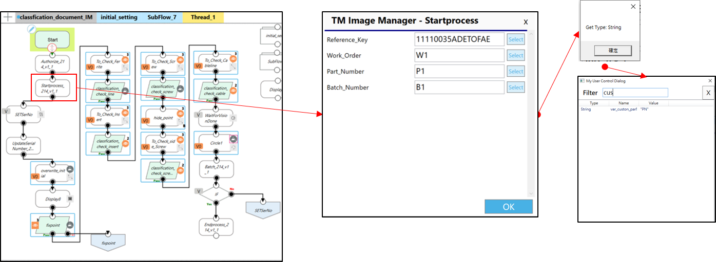
Startprocess node
- Fill in Reference_Key and make sure it’s the same Referency Key in Image Manager
- Click “Select”,choose the variables you set or you can type in value
- Once you have set the Part Number, Work Order, and Batch Number, you could search inspection records with those information in Image Manager
- Click “OK”
Edit Vision Job
- Taking the inspection of an electromagnetic ring as an example, utilize the display panel for precise positioning. Then move the robot to designated area for inspection
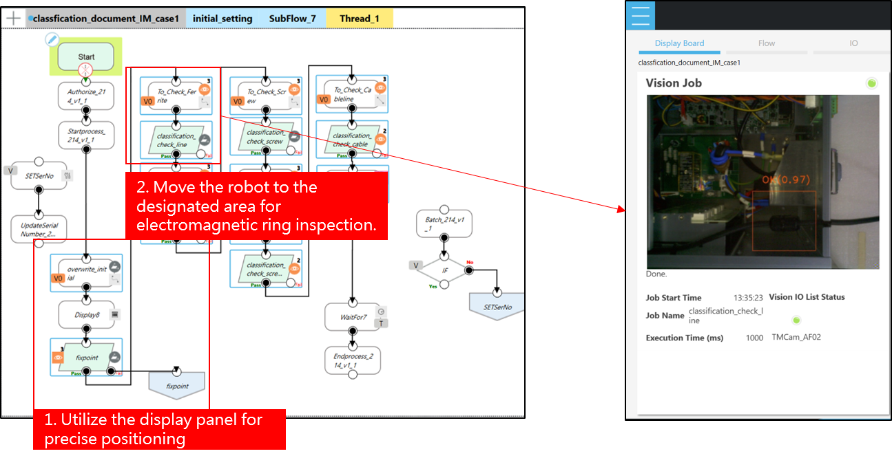
Taking the detection of an electromagnetic ring as an example. Utilize AI Classification to determine its presence. If the electromagnetic ring is detected, label it as OK; otherwise, label it as NG. After editing the vision job, it is recommended to select JPG format for saving the original images during visual data storage to reduce transfer time and storage space.
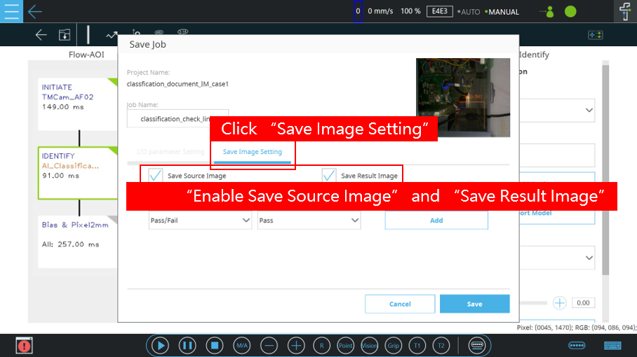
- Click “Save Image Setting”
- Enable “Save Source Image” and “Save Result Image”, then save the vision job.
Following the same approach, add each vision job to the TMflow and proceed to edit and save the vision jobs accordingly.
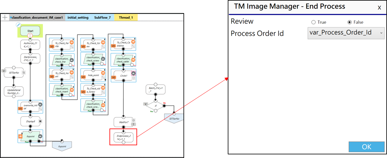
Endprocess node
- Choose whether to review the results in Image Manager. Since we just want to send pictures to Image Manager, select “False” here. By the way, Images without logic decision setting would display “FAILED” in Image Manager
- Select the “process_Order_Id” for this project (default value)
- Click “OK”
Execute Scenario 1 Project
When executing this project, if there are not any conditional statements for the vision jobs in TMflow, the underlying system will wait for 5 seconds and then send a “fail” signal. In Image Manager, navigate to Station Overview and click on your workstation.

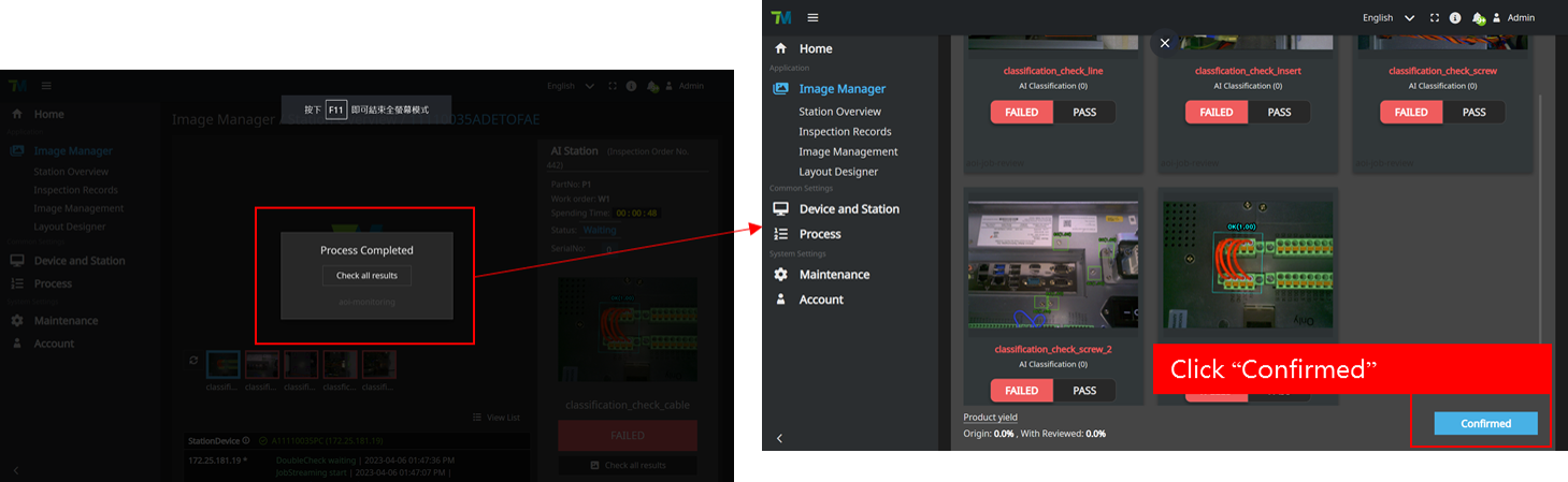
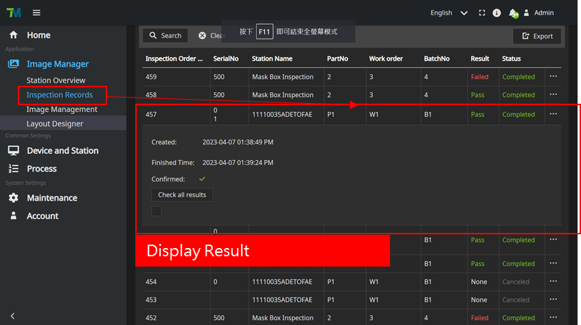
You can view the images you have sent and the AI judgment results in your workstation. Wait for the project execution to complete, then go to Inspection Records and locate your executed Inspection Order No. Click on it to view all the results.
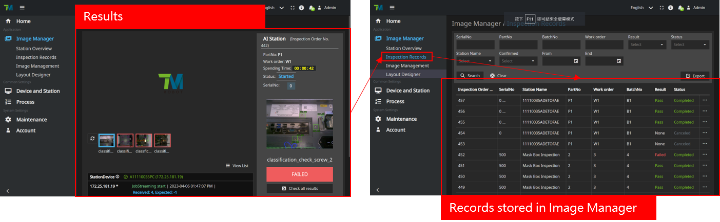
- During execution scenario 1, only the images were transmitted to Image Manager without undergoing review.
- The results of the tasks in execution scenario 1, when sent to Image Manager, are all set as “FAILED” by default.
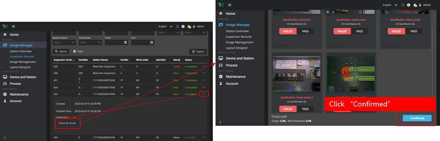
- When you click on “Check all results,” you can access the page where you can review the results and confirm them.
- Click Confirmed, complete the task.
Scenario 2: Inspect Control Box and Review the Result #
Authorize node
Edit the Image Manager Node and configure the Authorize node
- Fill in information
- Click ”OK”
- Click“Test”to test the connection
Startprocess node
- Fill in Reference_Key and make sure it’s the same Referency Key in Image Manager
- Click “Select”,choose the variables you set or you can type in value
- Once you have set the Part Number, Work Order, and Batch Number, you could search inspection records with those information in Image Manager
- Click “OK”
Edit Vision Jobs
Taking the inspection of an electromagnetic ring as an example, utilize the display panel for precise positioning. Then move the robot to designated area for inspection

Taking the inspection of an electromagnetic ring as an example. Utilize AI Classification to determine its presence. If the electromagnetic ring is detected, label it as OK; otherwise, label it as NG. After editing the vision job, it is recommended to select JPG format for saving the original images during visual data storage to reduce transfer time and storage space.
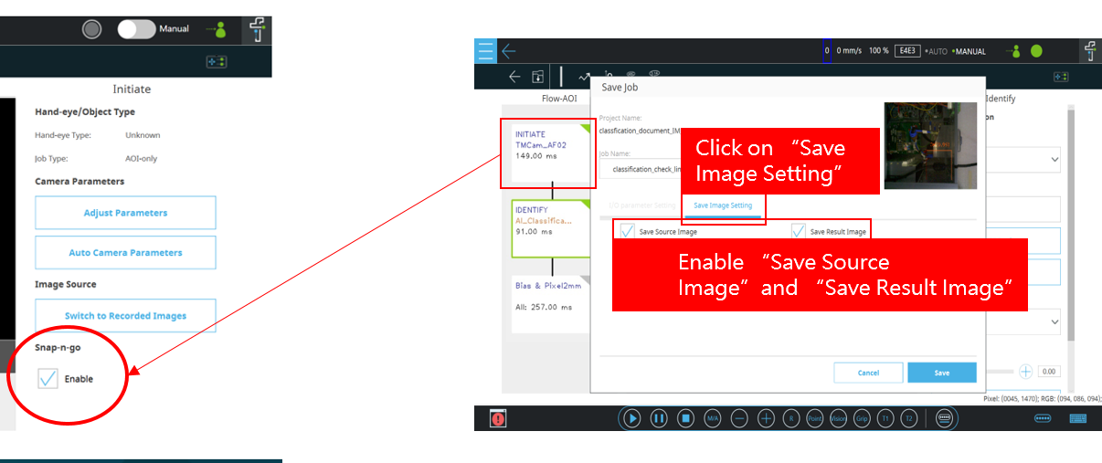
- Enable Snap-n-go in INITIATE
- Click “Save Image Setting”
- Enable “Save Source Image” and “Save Result Image”, then save the vision job
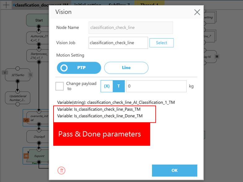
Due to the selection of “Snap-n-go,” you will receive two sets of parameters: “Pass” and “Done.” “Done” indicates whether the vision jobs have completed capturing images and processing results, while “Pass” indicates the success of the vision job execution.
Following the same approach, add each vision job to the TMflow and proceed to edit and save the vision jobs accordingly.
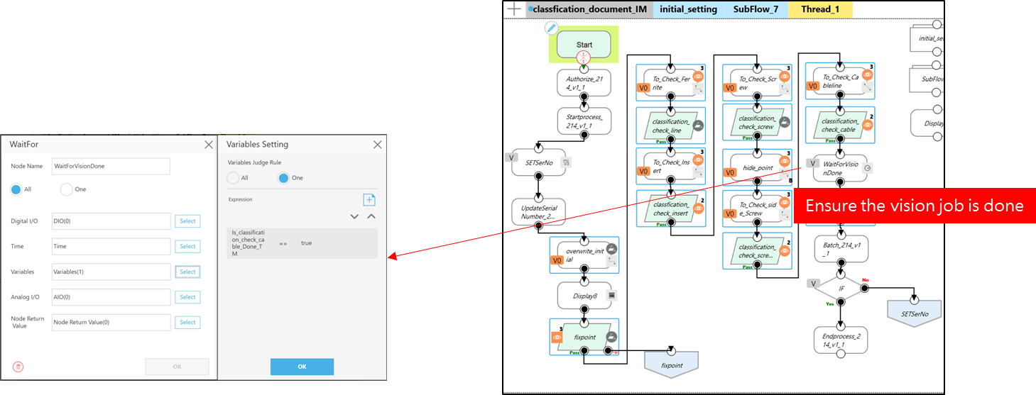
WaitforVisionDone node
- Is_classification_check_cable_Done_TM==“true
Ensure the completion of the final vision job to proceed with the next tasks.
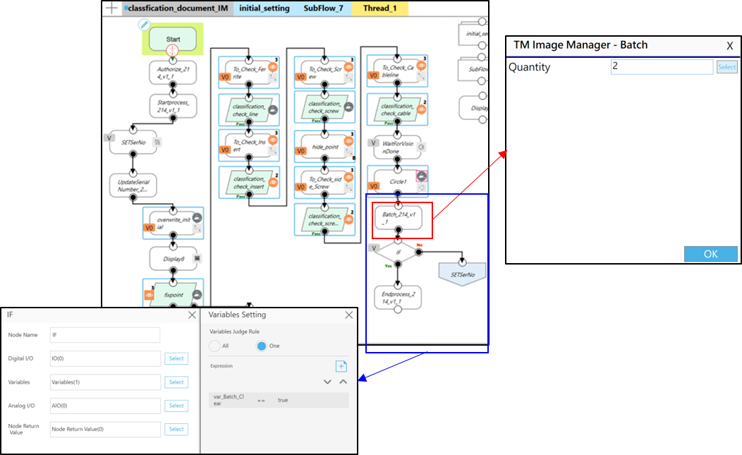
Batch node
- In scenario 2, there is a need to inspect five areas, each for two rounds of inspections. This suggests that on a single production line, there may be two electronic control boxes that require inspection.
- Set the quantity of this process to 2 to accommodate the desired number of inspections.
- Create an IF node below the Batch Node and input the following expression:
var_Batch_Clear==true
Yes path: connect to Endprocess
No path: connect to display panel locating
- Click ”OK”
Endprocess node
- Choose whether to review the results in Image Manager. In scenario 2, we will conduct a review by editing node in the Thread to determine if the results are categorized as “PASS” or “FAILED”. Therefore, click on “True” in this case.
- Select the “process_Order_Id” for this project (default value).
- Click “OK”

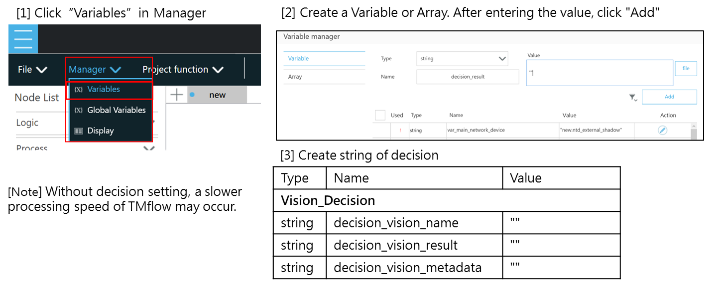
Thread – vision decision
Create a Decision variable to evaluate whether the vision job execution result is “NG”. If the vision job execution result is “NG”, send it to Image Manager as “FAILED”. If the execution result is “OK”, send it to Image Manager as “PASS”. You can perform a review in Image Manager.
You could customize a vision decision using the following steps. Let’s take the example of the task to inspect the presence of a magnetic ring (vision job name: “classification_check_line”). Repeat these steps for other tasks accordingly.
- Waitfor node
- Set the waiting time to 100ms, awaiting the vision job to execute.
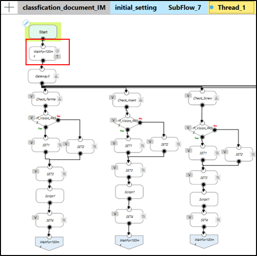
Gateway and Gateway condition
- Is_classification_check_line_TM_Done == true
- To check which specific vision job has been completed
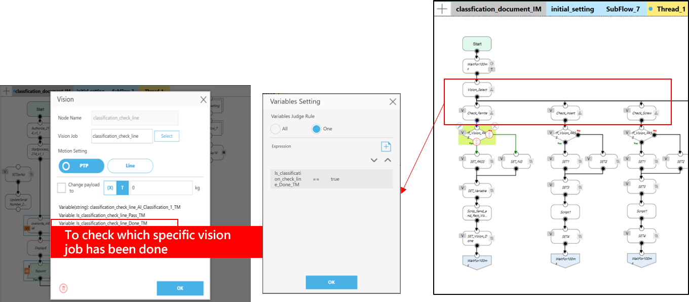
If node Decision
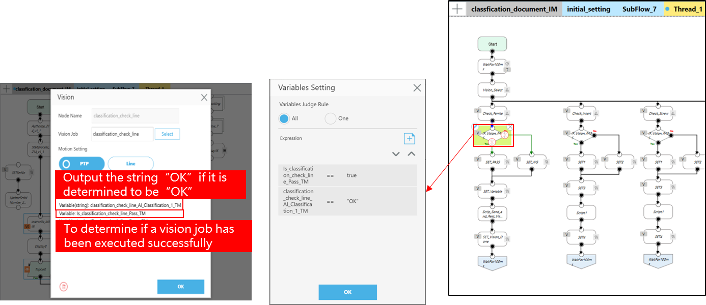
- is_classification_check_line_TM_Pass ==true
- To determine if a vision job has been completed. If it’s true then execute the following procedures.
- is_classification_check_line_AI_Classification_1_TM==“OK“
- Taking the presence of a magnetic ring as an example, if a magnetic ring is detected, it would be classified as “OK.” If no magnetic ring is detected, it would be classified as “NG.”
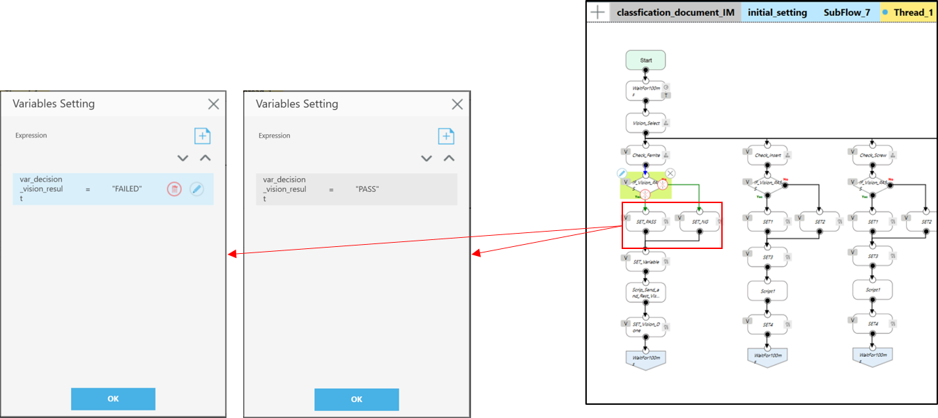
SET_PASS, SET_NG
- var_decision_vision_result ==”PASS”
- If the detection of the magnetic ring is classified as “OK,” it will be sent as “PASS” to the Image Manager.
- var_decision_vision_result ==”FAILED”
- If the detection of the magnetic ring is classified as “NG,” it will be sent as “NG” to the Image Manager.
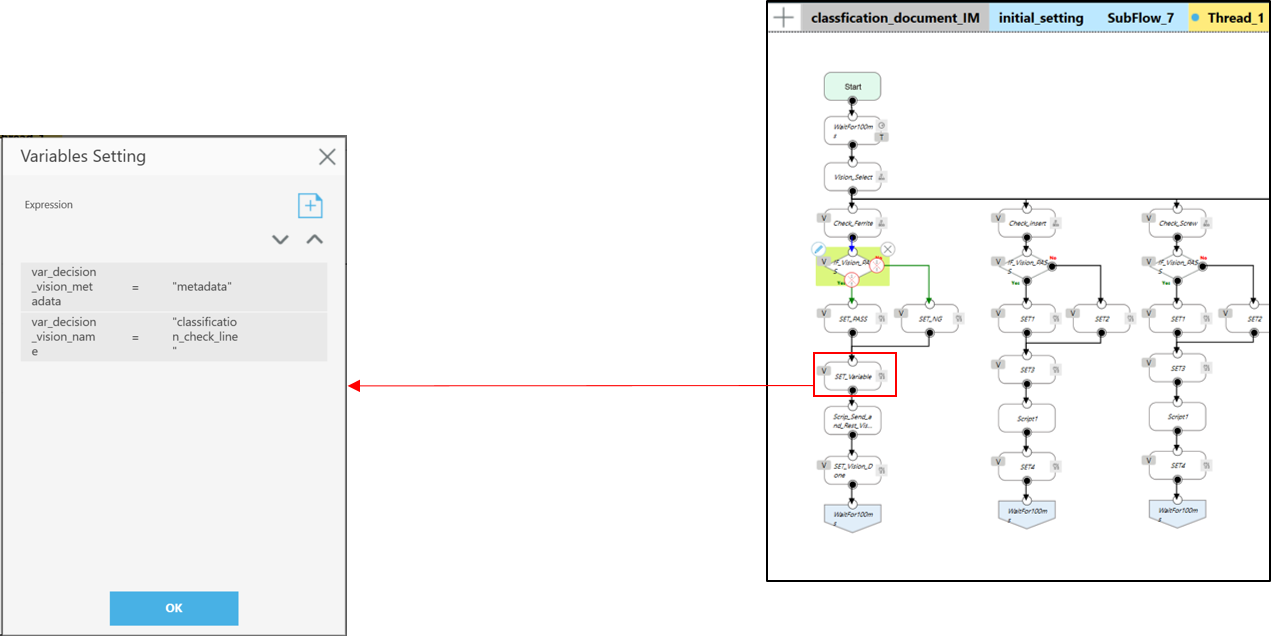
SET_Variable
- var_decision_vision_metadata = “metatdata“
- Send some reference information to the Image Manager.
- var_decision_vision_name =”classification_check_line”
- Enter the name of the vision job to be sent to the Image Manager.
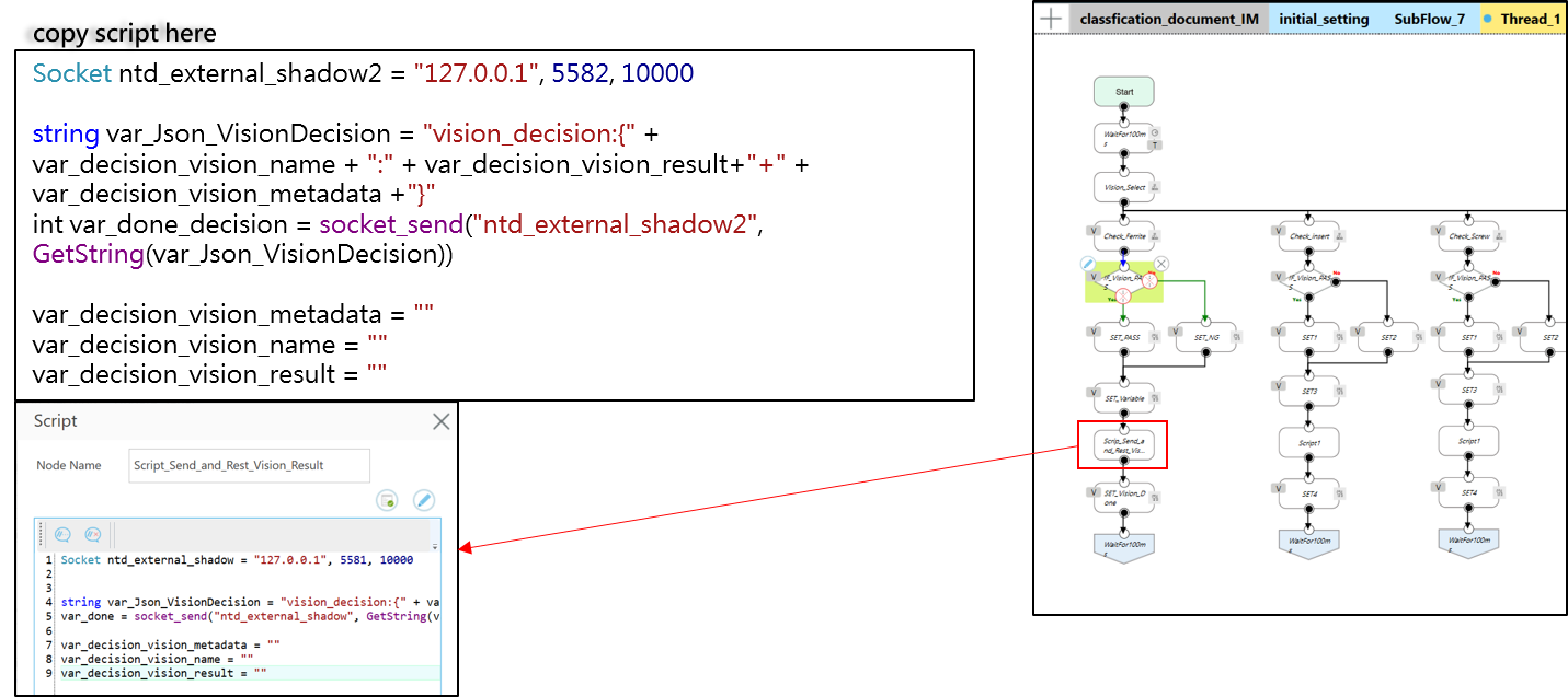
TMScript Name: Script_Send_and_Rest_Vision_Result
- Add the following settings: Use a decision variable and a Script node to send the inspection result to the Image Manager.
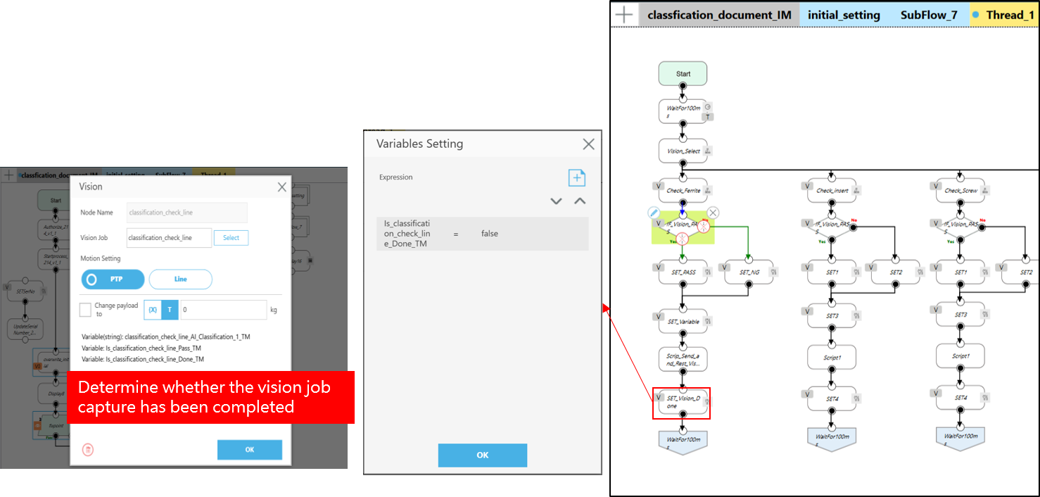
Set_Vision_Done
- is_classification_check_line_Done = false
- Deactivate the flag variable indicating the completion of the vision job, and wait for the flag to become true again to trigger the Logic Decision process.
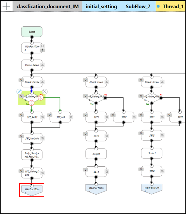
Back to Wait100ms node
- Return to waiting for 100ms to await the completion of the next vision job.
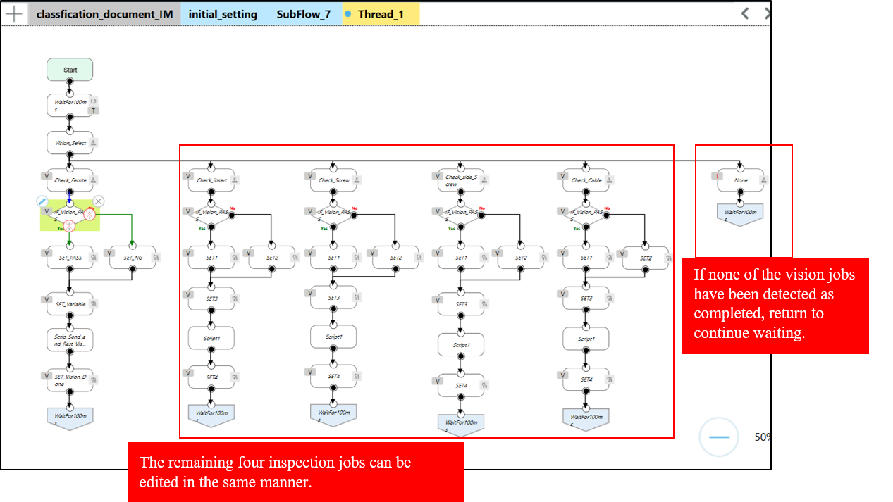
The remaining four vision jobs can be edited in the same manner.
Scenario 2: Inspect Control Box and Review the Result #
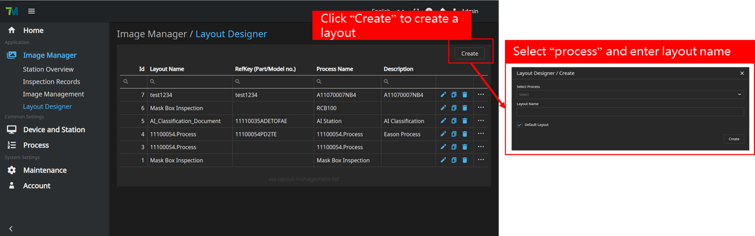
In scenario 2, you have the flexibility to customize the layout of the Image Manager’s real-time monitoring. To create a layout, ensure that the prerequisite steps have been completed, including setting up devices, workstations, and processes. Then, follow these steps:
- Click on “Create” to initiate the creation of a layout
- Select the desired process and enter the layout name.
- Access the Image Manager/Layout Designer/Layout Name page to further customize the layout according to your requirements.
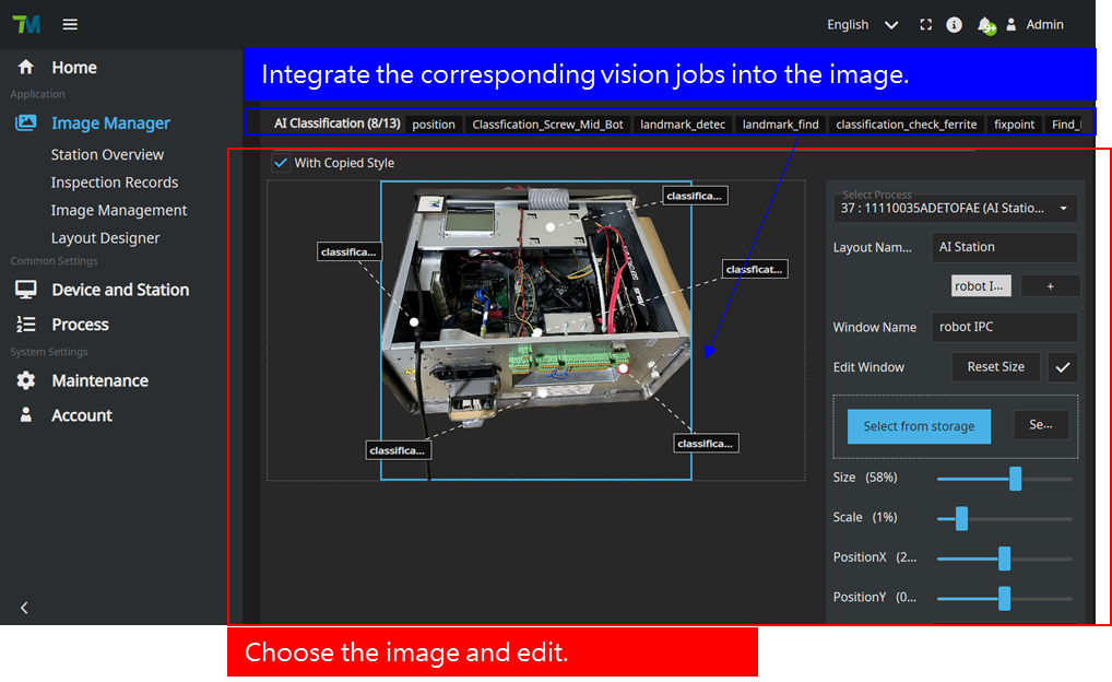
In the Image Manager/Layout Designer/Layout Name, you can design the layout page. During job execution, you can navigate to the Station Overview and access your workstation to view the results of the layout design.
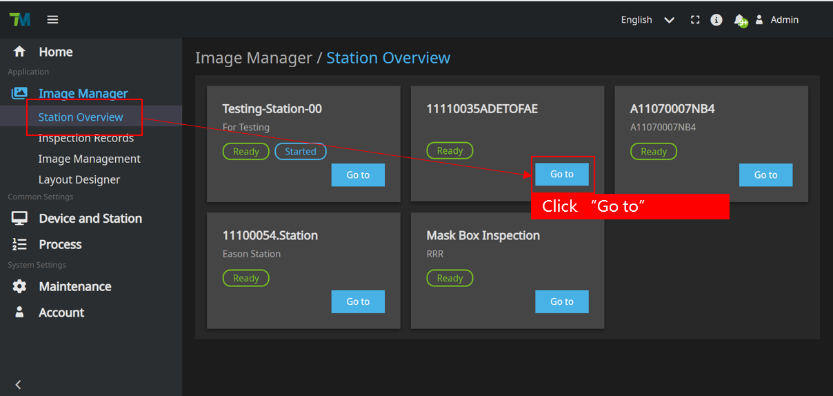
Execute this project and, in the Image Manager, select the Station Overview. Click on your workstation to access its details.
In your station, you can view the images you have sent and the AI assessment results. Since you have enabled review, after completing all vision jobs, a notification will prompt you to “Check all results.” If you have set up a layout, you can also see the images you have configured in the station. The images displayed indicate the ongoing vision jobs.
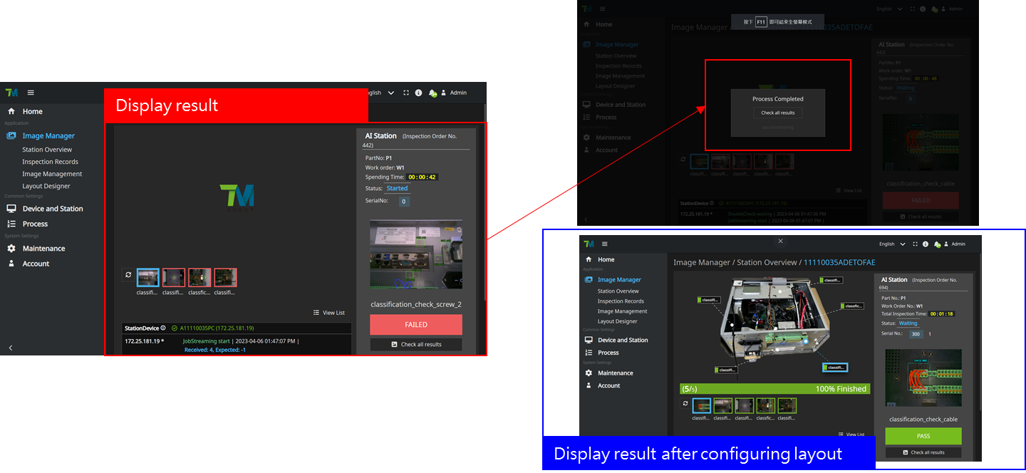
- During the execution of Scenario 2, images are transmitted to the Image Manager for review.
- If it determines that no magnetic ring is present, it classifies it as “NG” and sends it as “FAILED” to the Image Manager. Conversely, if the assessment results indicate that a magnetic ring is present, it is classified as “OK” and sent as “PASS” to the Image Manager.
- When the “Check all results” is clicked, you can access the corresponding page for review. You can perform review specifically for the cases that were classified as “FAILED”. Once the review is confirmed, you can click on “Confirmed” to complete the vision jobs.
- Similar to Scenario 1, you can find your Inspection Order No. (e.g., Inspection Order No. 457) in the Inspection Records. By accessing the Inspection Order, you can review the results. If there is at least one image classified as “FAILED” during the review confirmation, the result will be displayed as “FAILED,” indicating that there is a defect in this specific work order.
- Each Inspection Order No. represents a specific production line, and in this case, Inspection Order No. 457 represents one of those lines. By setting the quantity number to 2, it indicates that this production line consists of two electronic control boxes to be inspected. Therefore, there will be two sets of Serial Numbers assigned. In the next chapter, we will discuss how to customize the number of Serial Numbers.
Configuration of Inspection Order NO. and SerialNo #
Inspection Order No.
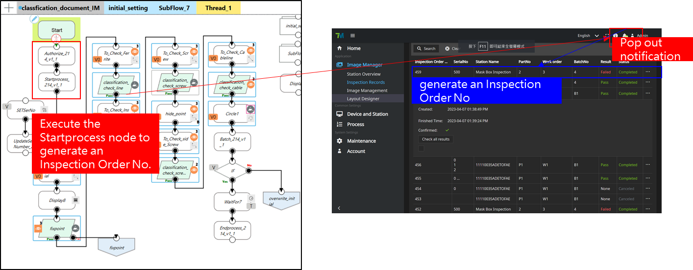
Each time you execute a Startprocess node, it will generate an Inspection Order No., which represents the start of a production line or the beginning of a inspection order.
If the UpdateSerialNumber node is not used, the default SerialNo will start from 0 and increment upwards

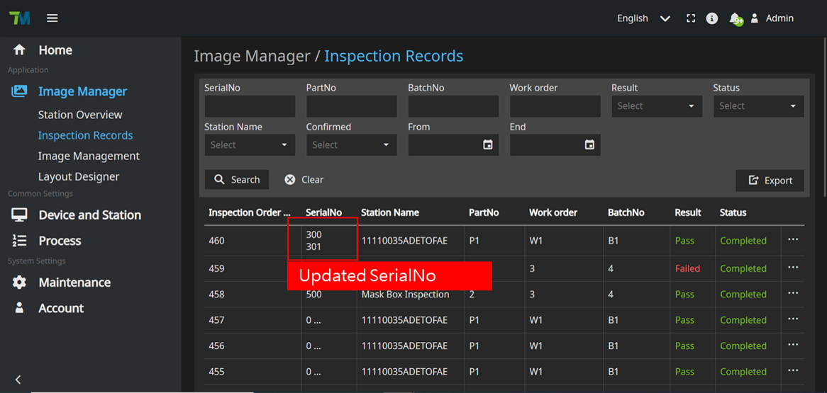
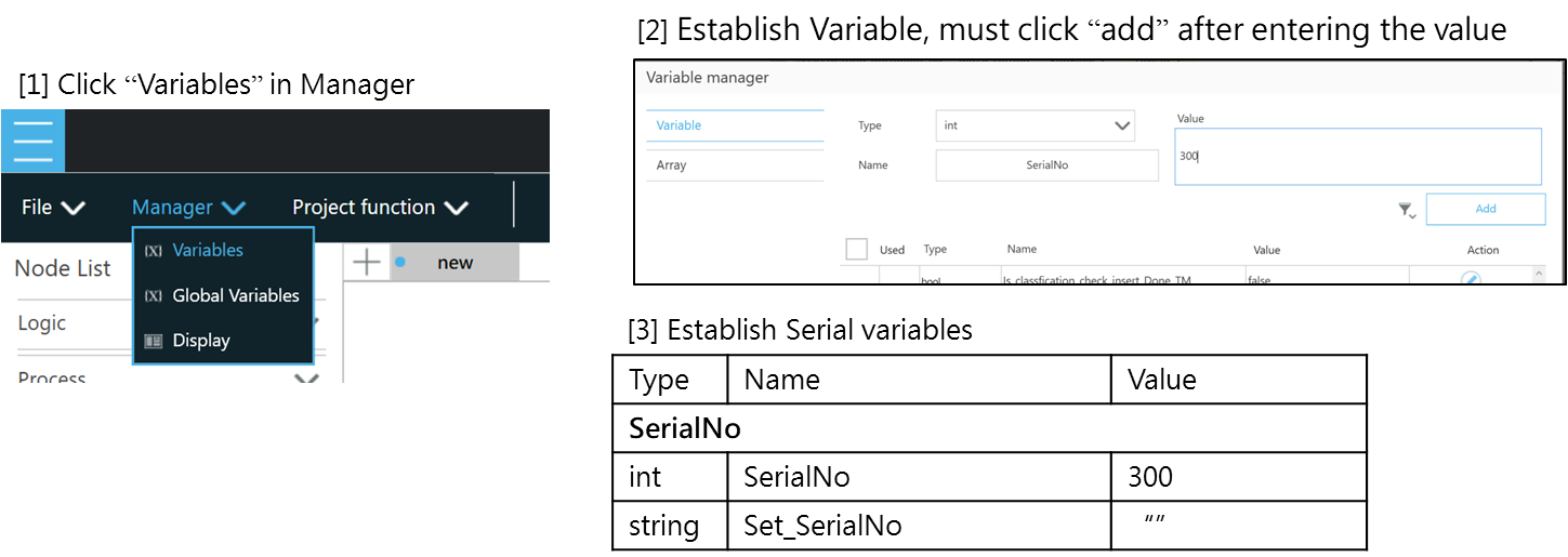
- To customize your own SerialNo starting from 300, you can use the UpdateSerialNumber node. Here’s an example of how to achieve this.
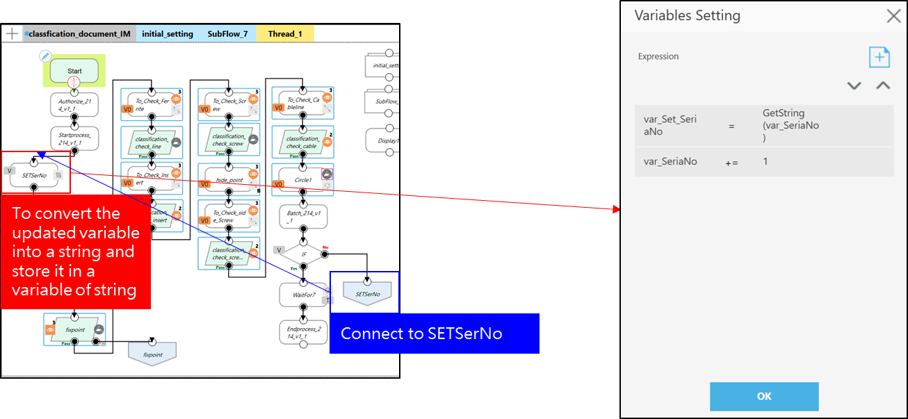
- To set up the variables for managing the SerialNo, including an integer variable and a string variable for updating the displayed SerialNo in the Image Manager
- Create an integer variable called SerialNo to store the numeric value of the SerialNo.
- Create a string variable called Set_SerialNo to store the string representation of the SerialNo.
To perform variable assignment within the SETSerNo node and update the SerialNo. If the batch is not completed, you have to connect “No path” to SETSerNo node in order to update SerialNo.
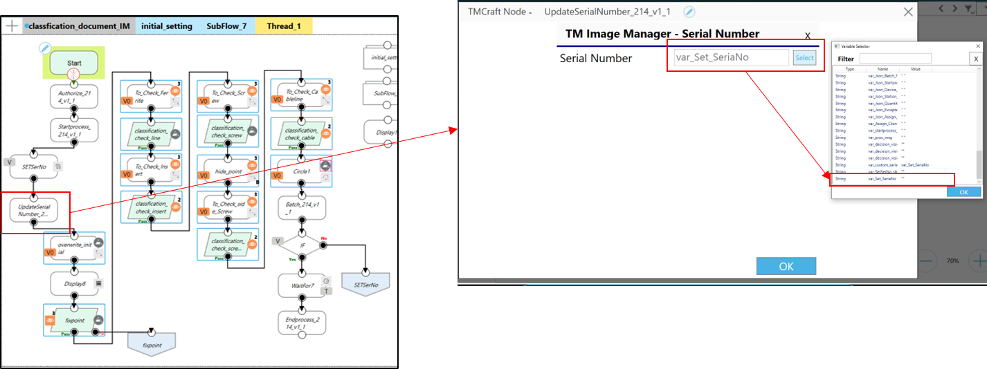
To configure the UpdateSerialNumber node and select the string variable you created
After executing the project, you will find that in the Inspection Record, the SerialNo starts from 300 and increments upwards.