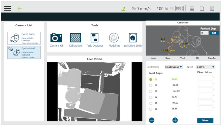
Step #1: After adding the vision job, in the vision screen, select the Ensenso 3D camera in the camera list at the left. Go to the task list and click Modeling.
Step #2: In the Select the way to get model data prompt, click From Camera to model the point cloud with the current 3D camera.
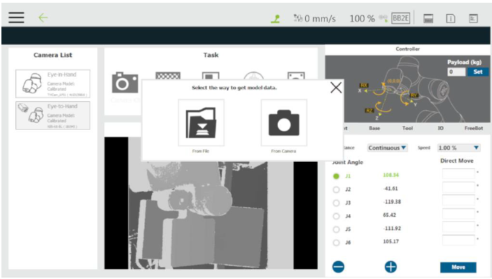
If selected From File, users can select the created model file from the Model List for editing. Please refer below for instructions.
NOTE:
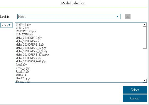
- If clicked From File, the window for selecting a file will prompt.
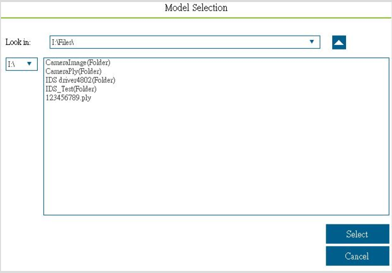
- Users can select the model file that has been edited from the folder Model in TMflow or read the model file from the flash drive labeled TMROBOT. The three file extension currently supports are .ply, .stl, and .obj. The following shows an example for reading from the flash drive. If it is a folder, it will be marked as one.
- After selecting the file, users will enter the Modeling tab to edit the saved point cloud file or the 3D drawing file obtained from another device.
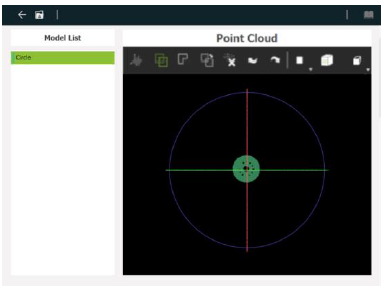
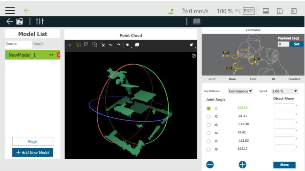
The currently opened file name displays under the Model Name. If it is retrieved from the camera, it will be filled in NewModel by default. The current 3D point cloud status displays at the right, and the R, G, and B of the three-circle colors correspond to the X, Y, and Z axes, respectively. There is no Align button, Add New Model button, and tab function under the Model List on this page.
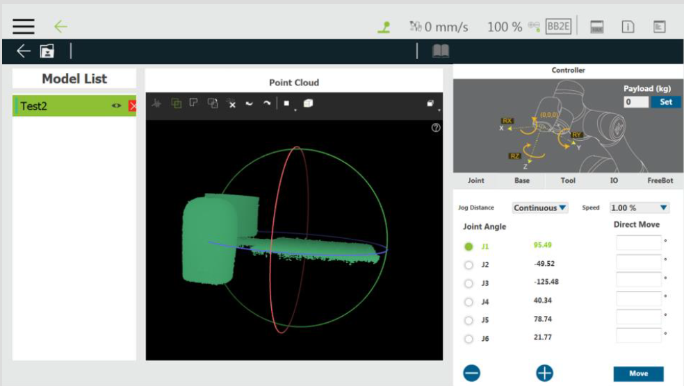
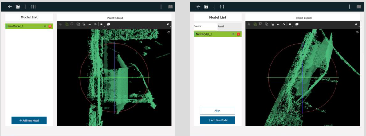
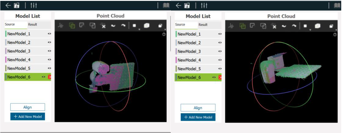
Step #3: In the Select the mode prompt, click Place Workpiece to go to the Modeling tab; or click Pick Workpiece to load the work plane and convert the point cloud base to the robot flange.
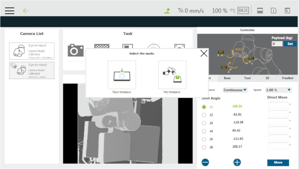
NOTE: After clicking Place Workpiece, there is no Align button and tabs under the Model List as shown as below left. Click Pick Workpiece and the screen will be shown below right.
※ The following steps take Pick Workpiece as an example
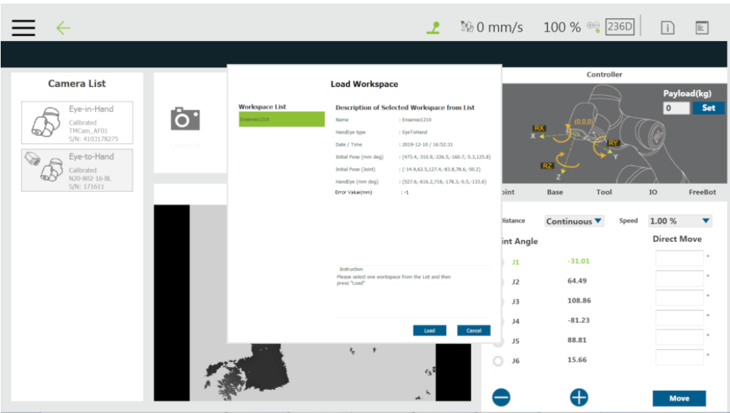
Step #4: In the Load Workspace prompt, click the desired hand-eye parameter to use. Generally speaking, the latest calibrated parameters are suggested to use. If the modeling effect is not good, please perform 3D Camera Eye to Hand Calibration again.
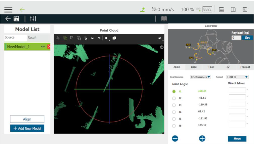
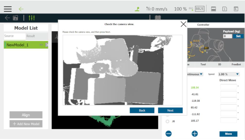
Step #5: After selecting the Eye to Hand parameters, users will enter the Modeling tab and take the first point cloud automatically. Users can click the right mouse button to rotate and the middle button to pan for the appropriate viewing angle adjustment.
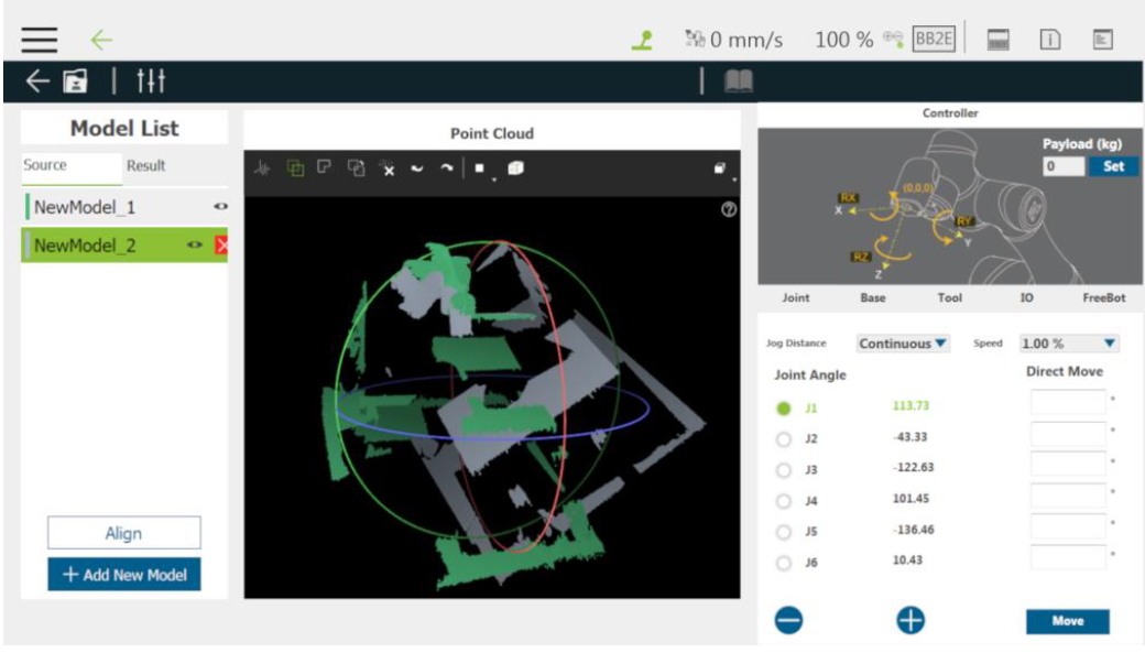
Step #6: Click Add New Model to take a new point cloud.
Step #7: Rotate and move the robot flange for the 3D camera to view different parts of the workpiece. Click Next to take this point cloud.
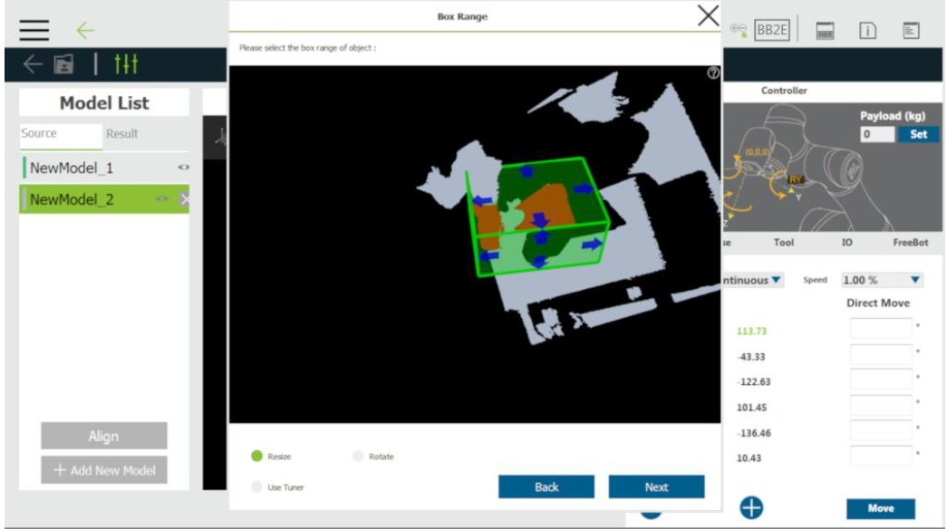
Step #8: Both old and new point clouds will be on the flange of the robot base. It is, therefore, required to remove the environmental point cloud. Click the point cloud cut ![]() icon to crop.
icon to crop.
Step #9: Use the mouse to adjust the position of the 3D Crop Box to make it contain the point cloud near the workpiece only. After adjusting, click Next to crop.
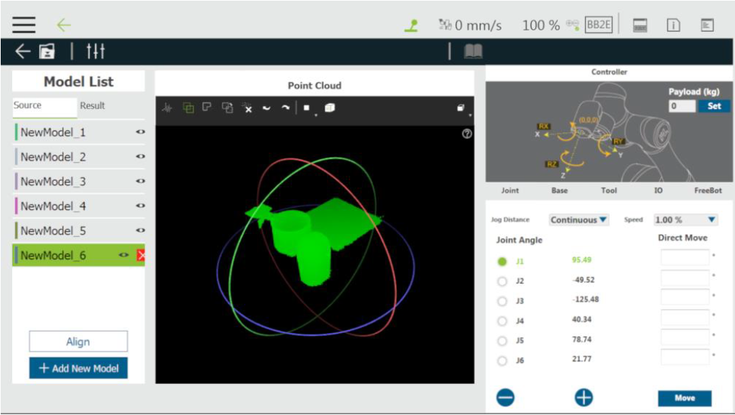
Step #10: 3D Crop Box will take effect on all point clouds. Please repeat the steps of turning and moving the workpiece as well as taking a new point cloud.
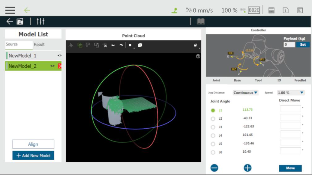
Step #11: Make sure that the point cloud information from various viewing angles of the workpiece is taken.
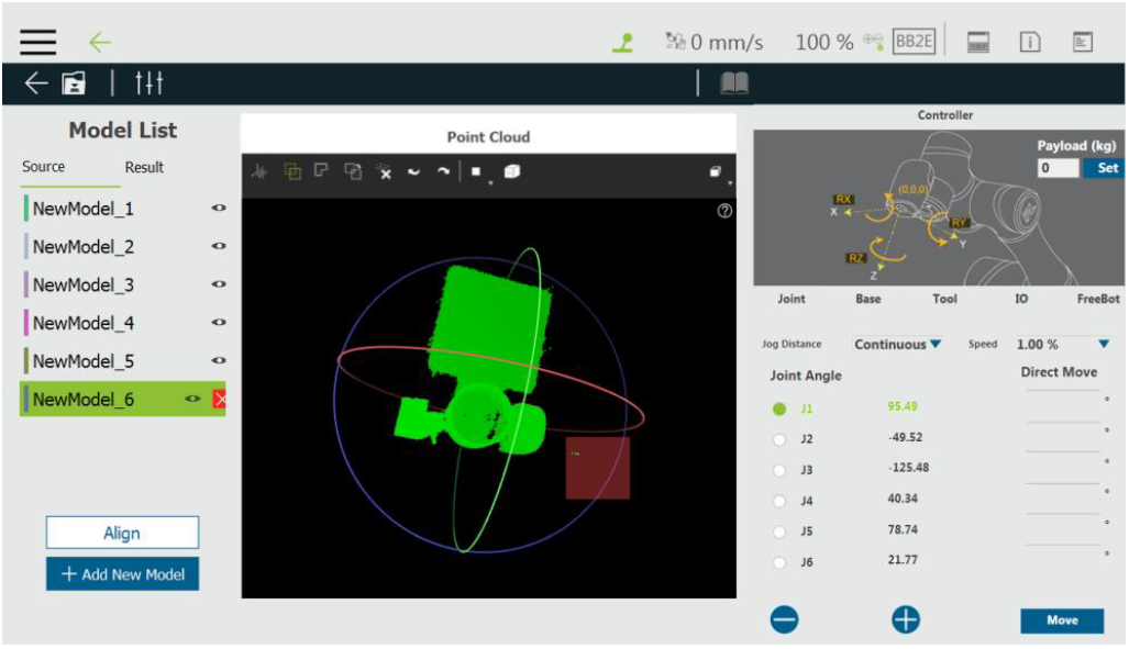
Step #12: Use the select tool and drag with the left mouse button on the screen to select the point cloud.
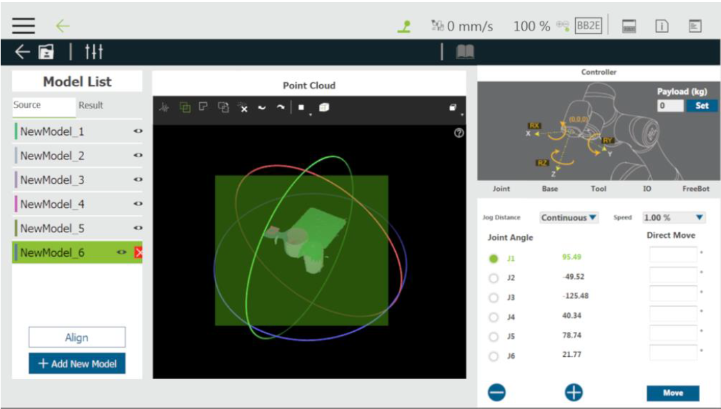
Step #13: The selected point cloud will be in green.
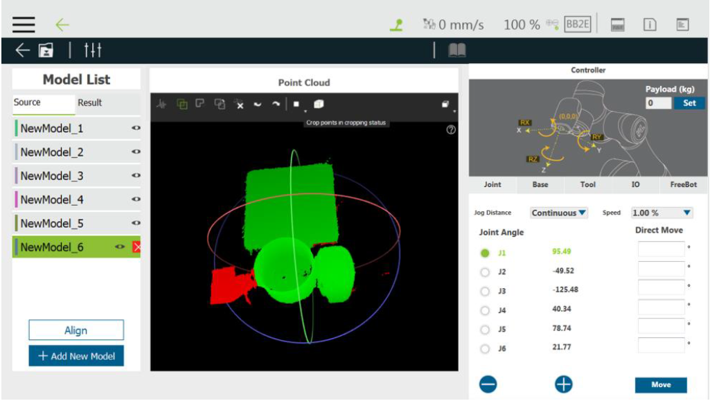
Step #14: Toggle to crop select tool to frame the part to be cropped in the selected point cloud.
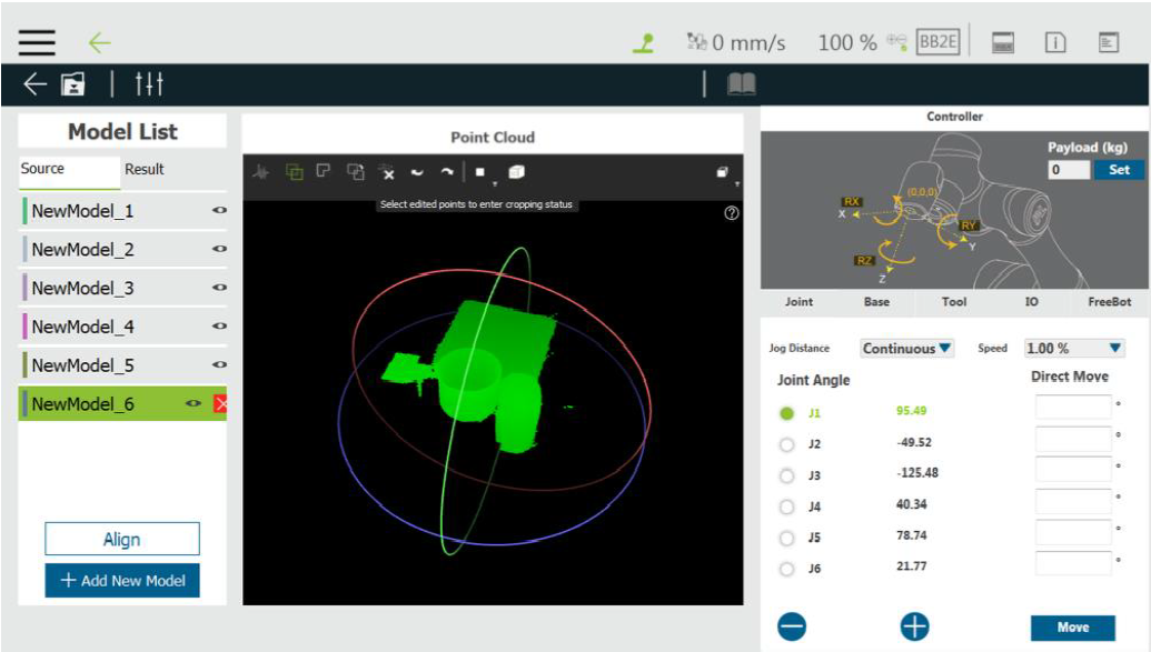
Step #15: The method to frame is the same as dragging the mouse button on the screen with the left button holding. Users can use the right mouse button to rotate and the middle button to pan for a suitable angle of view adjustment to crop the selection.
Step #16: The point cloud selected by the cropped selection frame will be in red.
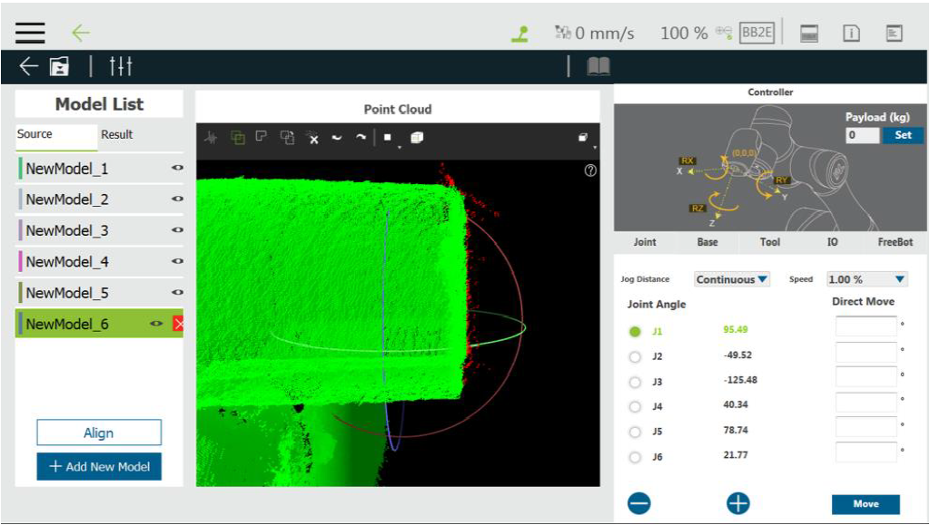
Step #17: There will be noise points on the edge of the point cloud of the workpiece inevitably, which will affect the modeling effect. Please try to remove them as possible.
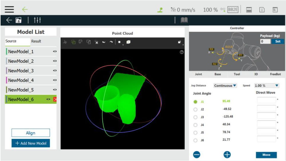
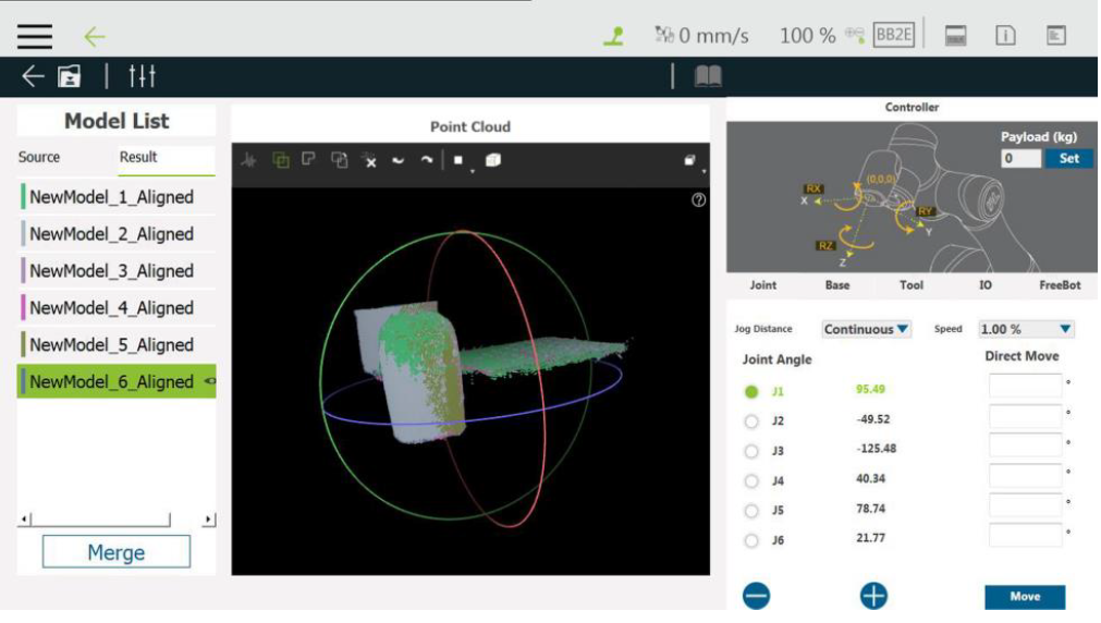
Step #18: Click the crop button to crop the red part. After cropping, click Align to make different point clouds fit each other.
Step #19: After clicking Align and checking OK, click Merge to combine the point clouds.
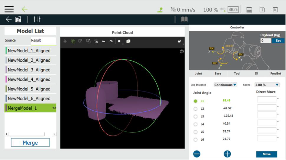
Step #20: After clicking Merge, there will be an additional merged point cloud in the point cloud list.
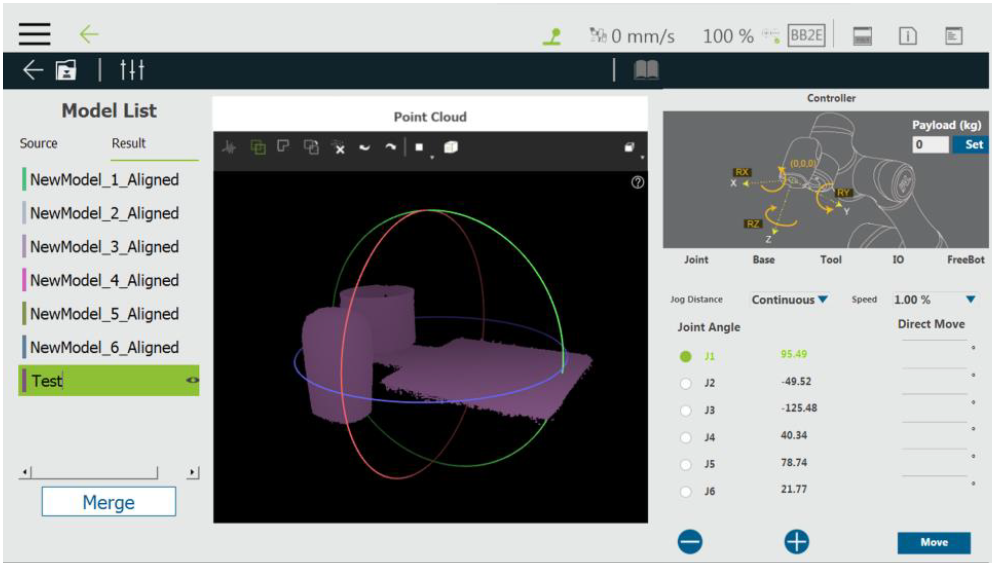
Step #21: Double-click with the left mouse button on the point cloud name to change the name, and then click Save to save the point cloud.
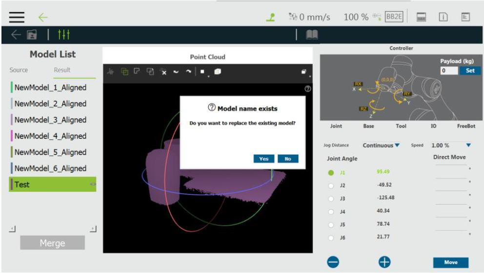
Step #22: If there exists a point cloud file with the same name already, users will be asked whether to overwrite.
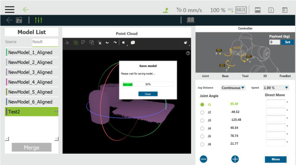
Step #23: It will take a little while to save the file. Please be patient.
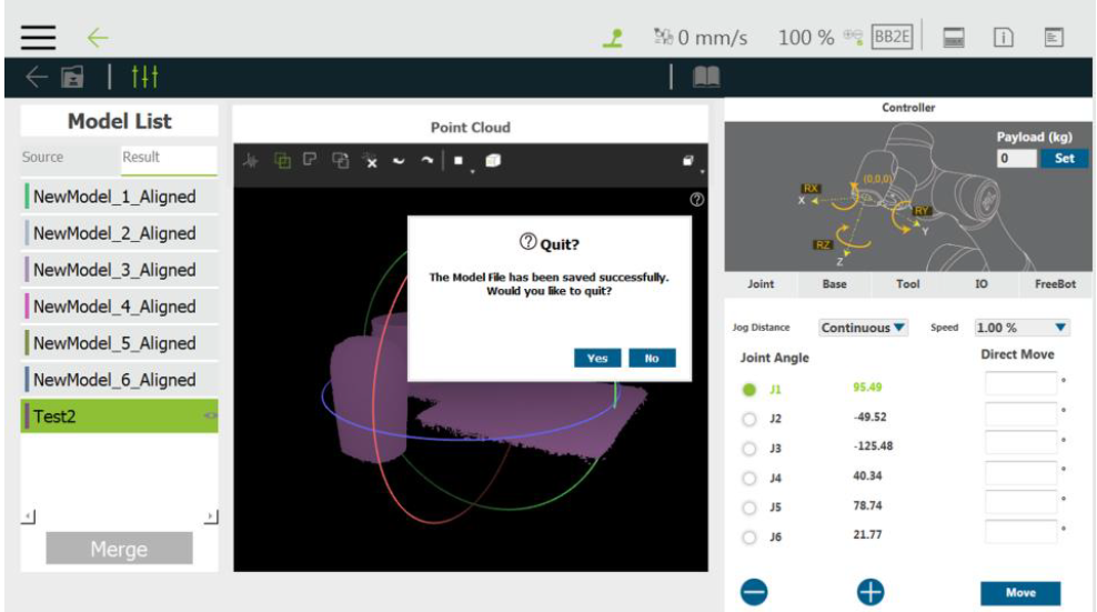
Step #24: After saving, users will be asked whether to leave the Modeling tab.