- Overview of Latest Welding Features
- Change Log & What's New
- Goal
- What is a Cobot Welding Solution?
- What is the Welding Node?
- Preparation
- Update the Welding Node
- Operating Welding Node
- An Example of the Welding Solution
- Overview of the system
- Item#1 Robot and Cover
- For High-Frquency Power Source(TIG)
- Item#2 Power Source / Item#5 Wire Feeder/ Item#6 Torch
- Item#3 Teach Pendant
- Item#4 Table and Base/ Item#7 Flange Tool / Item#8 CO2 Tank and Welding Wire/ Item#9 Workpiece and Jig
- Item#10 Wiring & Integration
- Definition of I/O on TM Robot
- Manual Testing & Programming
- Example1 : Linear Welding
- Example2 : Linear and Circular Welding
- Example3 : Multilayer Welding for Fillet Weld
- Real Welding
- Auto Path Generation with a Laser Profiler
- Common Q&A
- Does TM support my welder?
- Could I use EtherCAT protocol with my welder?
- Does TM support welding type MIG/MAG/CO2/TIG?
- Does TM support weaving(zig-zag)?
- Does TM support seam tracking?
- Could I use robot to do thin part welding or Aluminium-based welding?
- Could I use vision job with Welding Node?
- Suggested welders that compatible with TM?
- What is the rotational speed?
- The Cobot Is Interfered by The TIG Machine.
Examples are valid for:
TMflow Software version: Refer to Preparation section.
TM Robot Hardware version: HW3.2 / HW5.02 (with TM12S-HW5.02 / TM12-HW3.2 in this article)
Other specific requirements: Refer to Preparation section below.
Note that older or newer software versions may have different results.
Overview of Latest Welding Features #
| Item | Catogory | Features | Description |
| 1 | User Interface | Simple interface | Integrated user interface for welding application. Clear and simple.
|
| 2 | Operation | Leverage built-in buttons for hand guiding | For hand guiding, adding welding points, moving points. Intuitive operation.
|
| 3 | Motion | Straight line welding | For straight lines, could combine multiple lines also.
Can do horizontal welding/vertical welding/overhead welding, etc..
|
| 4 | Motion | Circular welding | Use threes points to create an arc.
|
| 5 | Motion | Spline welding | Create smooth curves with multiple points.
|
| 6 | Welding | Recipe | Recipes could be assigned to different seams. Parameters including: JOB, START CURRENT/VOLTAGE, CRATER, WAIT TIME, FlOW-TIME, SPEED.
Store different recipes for different workpieces/tasks.
|
| 7 | Motion | Weaving | Weaving patterns could be applied on welding paths.
|
| 8 | Motion | Multilayer | Multilayer could be applied on welding paths with different parameters.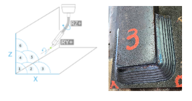 |
| 9 | User Interface | Communication with the power sources | Configure digital I/O and ModbusTCP to communicate with a 3rd-party power source. The cobot controls the power source directly.
|
| 10 | User Interface | Customized arc-trigger events | Leverage predefined arc event(START, CHECK, CRATER, END, OFF).
|
| 11 | User Interface | Gadgets for testing the power source | For testing the power source, including GAS, WIRE.
|
| 12 | User Interface | Auto path generation with a laser profiler | Create a single and curved welding path automatically. An additional laser profiler is required.
|


Change Log & What’s New #
| Date | Description | Change Log |
| 2026-3-10 | WeldNode V2.0.3.1 release
WeldThread V2.0.2.5 release WeldService V1.0.3 release scanCONTROL_Toolbar_V1.0.0.0 release |
WeldNode WeldThread WeldService Toolbar |
| 2025-8-29 | V2.0.2.7 release | |
| 2025-7-16 | V2.0.2.2 release | |
| 2025-1-09 | V2.0.1.5 release | |
| 2024-5-28 | V2.0.0.5 release | |
| 2023-10-02 | V1.0.0.6 release |
Here to download the latest welding node > ![]()
[1] 2023-10 v1.0.0.6 First release. #
[2] 2023-12-07 v1.0.0.61 Darken the color of function tab.
[3] 2023-12-12 v1.0.0.62 Fix the issue of TMcraft “comma” when operate on european lanaguage TMflow Client.
[4] 2024-05-28 v2.0.0.5 Improve UI in Path tab. #
[4-1] New layout for PATH tab.
[4-2] Add JOB variable in RECIPE. You can use it to control the JOB in the welder. A TMflow variable will be created automatically.

[4-3] Add WaitTime Left and Right. If using weaving, now the weld speed will be applied on the direction of Step, not the speed on the hypotenuse.

[4-4] If you are going to use ModbusTCP in Welding Node, make sure you create it both in TMflow and Welding Node. Or there will be an error when running the TMflow project, missing the definition of ModbusTCP device.

[4-5] Add “Load/Upload” configuration mechanism for Welding Node, the file will be stored under TMflow/TextFiles. The configuration data could be shared in different Welding Node now.

[4-6] Fix some display bugs in UI and numpad.
[5] 2025-01-09 v2.0.1.5 Improve UI and add some new features. #
[6] 2025-07-16 v2.0.2.2 Fix some bugs and some new features. #
[6-1] Points can be imported/exported now.
[6-2] Add beta function: pages for laser seam tracking and Tip adjustment.
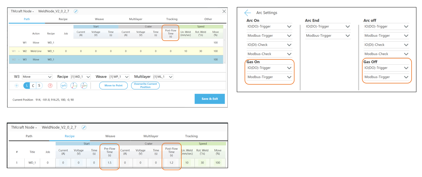
[6-3] Add Pre-flow blowing time and after-flow blowing time.
[6-4] Base/TCP now can be assigned.
[7] v2.0.2.7 Fix some bugs and some new features. #
[7-1] Remove Other > TCP adjustment page.
[7-2] Separate GasOn/Off events from ArcOn/Off events, for pre-flow/after-flow functions.
[7-3] Add Japan(JP) language.
[7-4] Improvemts and bug fixs: please refer to change log above.
Goal #
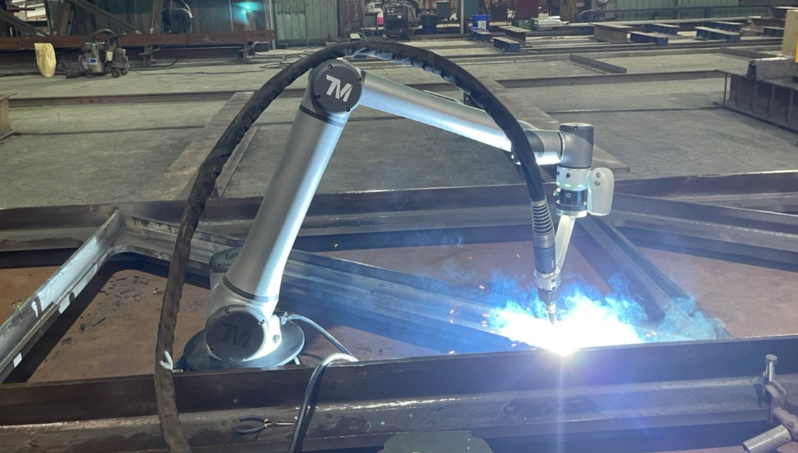
This is a tutorial intended for system integrator(SI). In this article, we share the idea on building welding soultion with Panasonic welding power source(welder) for your reference. It’s not limited to the Panasonic welder, it could be any welder with similar functions.
The example below is not an official product from TM, please consult your welding expert locally about the welding equipment and welding knowledge. TM provides software package only.
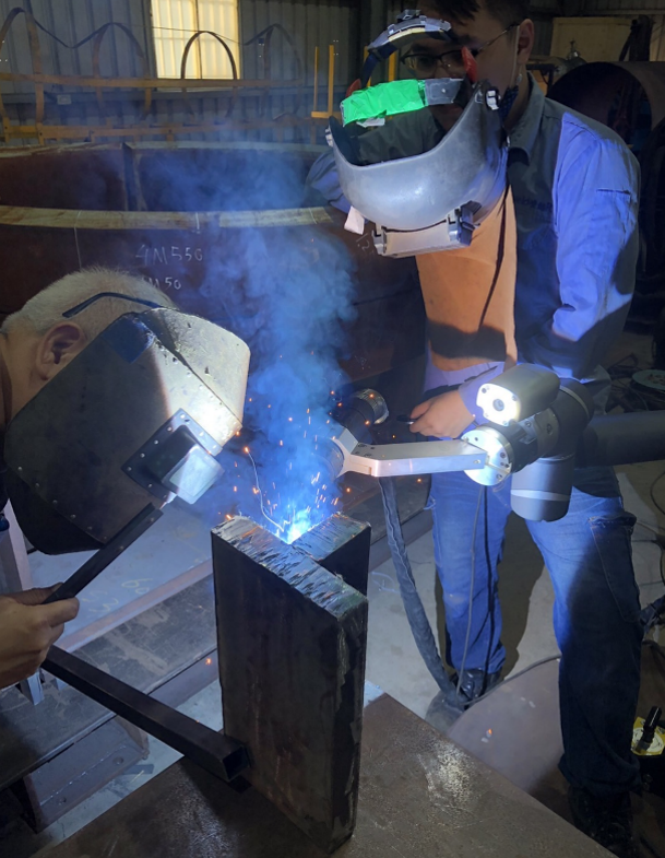
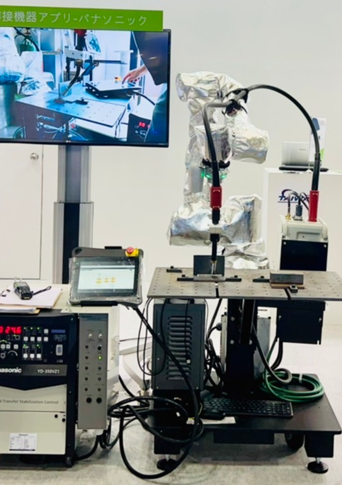
TM12S Working at the Site
How to Weld in 1 Minute?
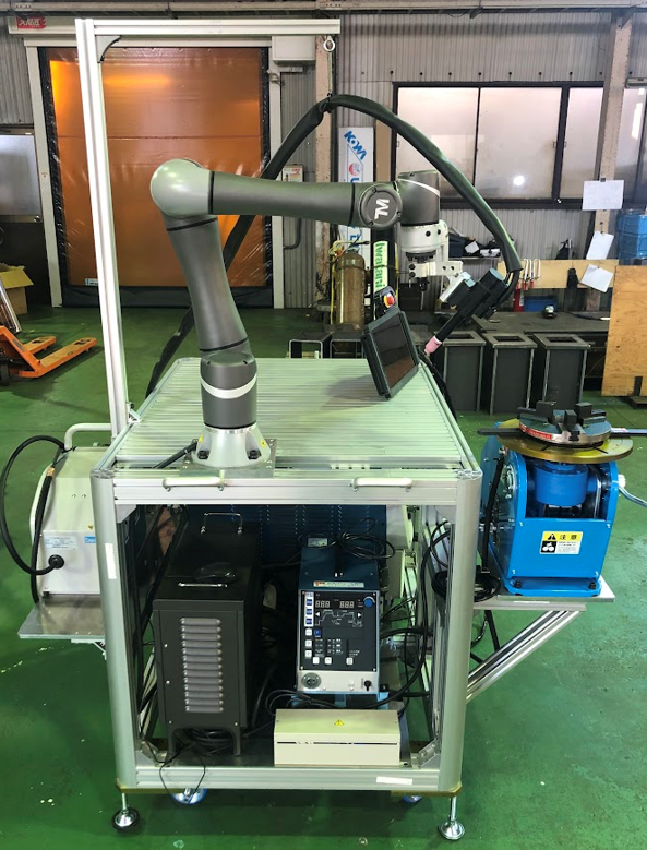
What is a Cobot Welding Solution? #
It is a ready-to-use welding solution, with a cobot on it and holding a torch for arc-welding process such as MIG/MAG/TIG.
EVERYONE CAN USE IT
Even an entry-level operator could teach and program the cobot with basic training, no more advanced robot programmer needed. Suitable for small and medimum-sized enterprise before large-scale investment.
TEACH BY HAND
Show the cobot where to weld, and start welding in minutes. Make welding easy!
LIGHT WEIGHT AND COMPACT DESIGN
Unlike industry robot, it’s possible to mount the cobot on a cart or magnet to get mobility. Thanks to the collabrative design of cobot, safety fence is no longer mandatory and this reduces the total cost of solution.
Everyone Can Operate it
Systematic Overview of the Welding Solution
What is the Welding Node? #
A Software Welding Package on TM Cobot.
The Welding Node on TMflow2 is a software package especially for arc-welding application running. No license needed.
With the Welding Node, you could leverage following functions:
- End button actions for welding/move point teaching
- Specific setting UI for editing welding parameters
- Ready-to-use configurator for setting I/O to communicate with your welding machine
Operating Welding Node with Ease
Preparation #
Before implementation, there are recommended items to study and prepare:
- TM robot HW3.2/HW5.02
- Download the Welding Node Package to a USB stick(named with TMROBOT)
- Follow steps in Operating Welding Node for installation
| Welding Node Version | Supporting TMflow Version |
| V2.0.3.1 Download Here |
V2.22 and later |
| V2.0.2.7 Download Here |
V2.22 and later |
| V2.0.2.2 Download Here |
V2.20 and later |
| V2.0.1.5 Download Here |
V2.20 and later |
| V2.0.0.5 Download Here |
V2.18 and later |
| V1.0.0.6 Download Here |
V2.14 and later |
- Experienced in arc welding(or consult local welding expert)
- Welding & safety equipements for welding application
- Necessary protection for the robot and controller
- Panasonic Welder 350VZ1, torch system, feeder and wiring
- External I/O for digital and analog output, wiring
- Set correct TCP data with the torch and base
If you did not import any TextFiles(or you are not sure) before, import any TextFiles(also in this package zip file above) and then delete this TextFiles, then reboot. Every new robot should do this once or there will be an error when you are using File Explorer in Welding Node >Other.
For Auto Path Generation with a Laser Profiler #
| Welding Node-Thread | Supporting TMflow Version |
| V2.0.2.5 Download Here |
V2.22 and later |
| Welding Service | Supporting TMflow Version |
| V1.0.3 Download Here |
V2.22 and later |
| Toolbar | Supporting TMflow Version |
| V1.0.0 Download Here |
V2.22 and later |
| TCP Files | Supporting TMflow Version |
| V1.0.0.0 Download Here |
V2.22 and later |
| TMflow Project – Sample | Supporting TMflow Version |
| V1.0.0.0 Download Here |
V2.22 and later |
| TMflow Project – Calibration | Supporting TMflow Version |
| V1.0.0.0 Download Here |
V2.22 and later |
=======================================
Update the Welding Node #
If you have old Welding Node version and you want to update it, follow these steps:
- Record the settings in previous Welding Node.
- Remove the old Welding Node in TMcraft.
- Import the new Welding Node in TMcraft.
- Keyin the settings in new Welding Node.
Related materials:
- TMflow Software Manual – for basic operation of TM Cobot, could be downloaded at Download Center

- How To Add IO Channels With External IO Device Via MODBUS TCP/IP? – for adding external I/O devices on Modbus, refer to Technical Documents
Operating Welding Node #
TMflow2 #
TM Cobot system : TMflow2.14.7400(and later) is neccessary to run Welding Node. For HW3.2 and TMflow1, please contact TM agent, engineering or sales team to upgrade to TMflow2. For robots with HW5.02, they come with TMflow2.
Software Package Installation #
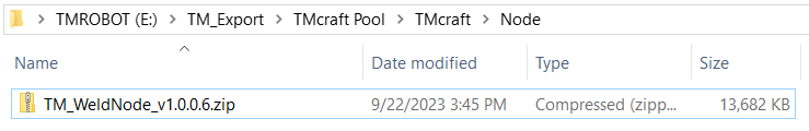
- Copy the Welding Node(i.e., WeldNodeVxxxx_XXXXXXXX.zip) file in Preparation, copy to the path TM_Export/TMcraft Pool/TMcraft/Node to a USB stick named with TMROBOT. Insert the USB stick to the robot controller.
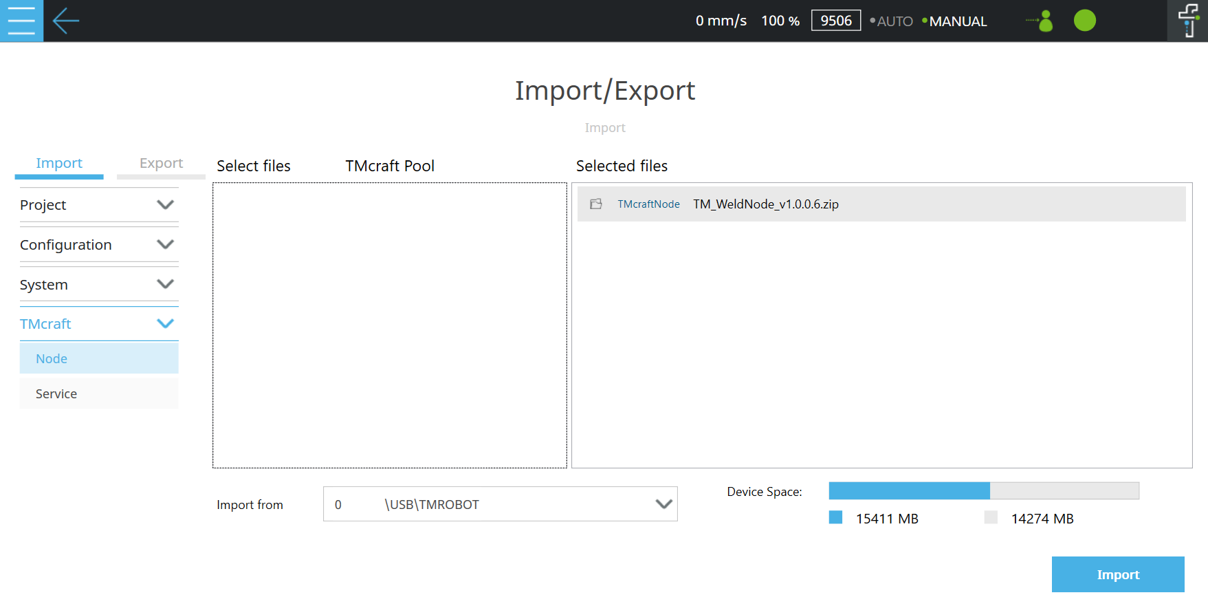
- On TMflow2, navigate to Menu/System/Import/Export, and import the file from USB stick.
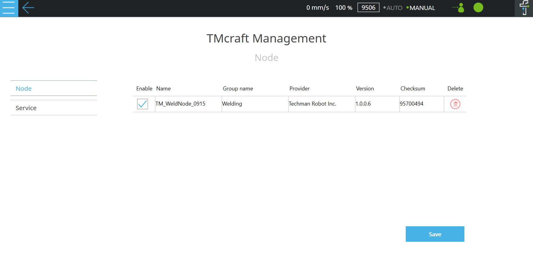
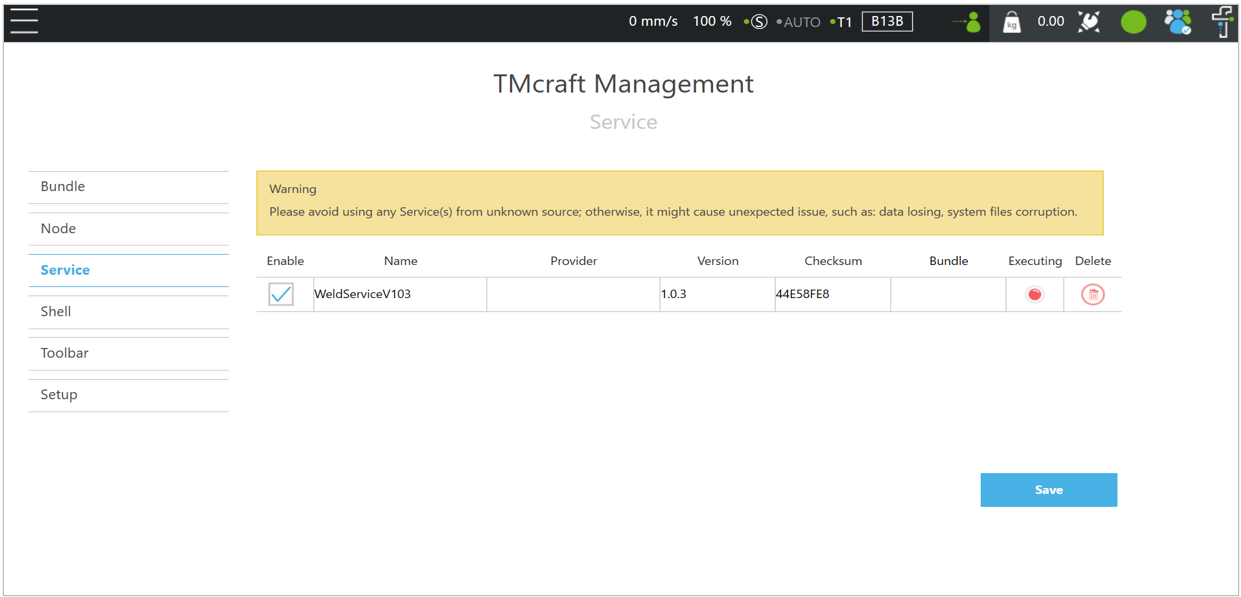
- Navigate to Menu/Configuration/TMcraft Management, enable the Welding Node. Please delete old version of Welding Node or there will be multiple Welding Node.
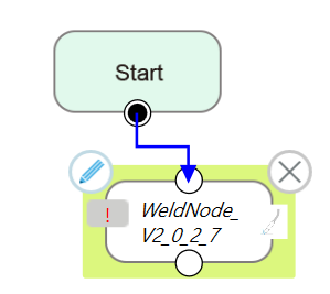
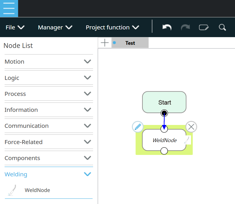
- Navigate to Menu/Project, create a TMflow project, there will be a Welding Node in the group Welding. Drag and drop it under the start node. Click the Pencil icon on Welding Node to go to the programming UI.
Software Package Installation with Auto Path Generation #
- Install the Welding Node in previous steps.
- For following steps, create cooresponded folders if you don’t have them.
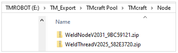
- Copy the WeldThread(i.e., WeldThreadVxxxx….zip) file in Preparation, paste it to the path TM_Export/TMcraft Pool/TMcraft/Node to a USB stick named with TMROBOT. Insert the USB stick to the robot controller.
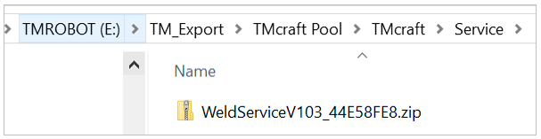
- Copy the WeldService(i.e., WeldServiceVxxxx….zip) file in Preparation, paste it to the path TM_Export/TMcraft Pool/TMcraft/Service
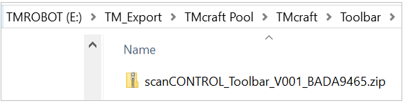
- Copy the Toolbar(i.e., XXX_Toolbar_Vxxxx….zip) file in Preparation, paste it to the path TM_Export/TMcraft Pool/TMcraft/Toolbar
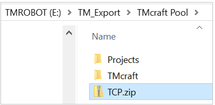
- Copy the TCP(i.e., TCP.zip) file in Preparation, paste it to the path TM_Export/TMcraft Pool
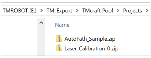
- Copy the TMflow Projects(i.e., XXX.zip) file in Preparation, paste it to the path TM_Export/TMcraft Pool/Projects
- On TMflow2, navigate to Menu/System/Import/Export, and import the files from the USB stick.
- TMflow Project : Laser_Calibration
- TMflow Project : AutoPath_Sample
- TCP : Weld_Tool
- TCP : Laser_Tool
- TMcraft Node : WeldNode_
- TMcraft Node : WeldThread_
- TMcraft Service : WeldService_
- TMcraft Toolbar: scanCONTROL_Toolbar_
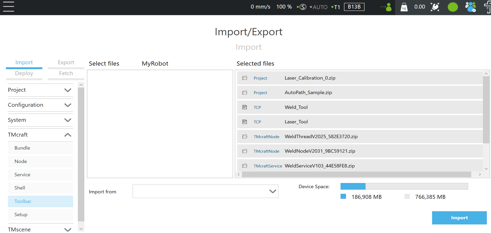
- Click Import
- Go to Menu/Settings/Configuration/TMcraft Management, activate following items:
- TMcraft Node : WeldNode_
- TMcraft Node : WeldThread_
- TMcraft Toolbar: scanCONTROL_Toolbar_
- TMcraft Service : WeldService_
- Apply
- Reboot
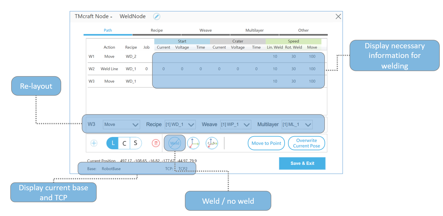
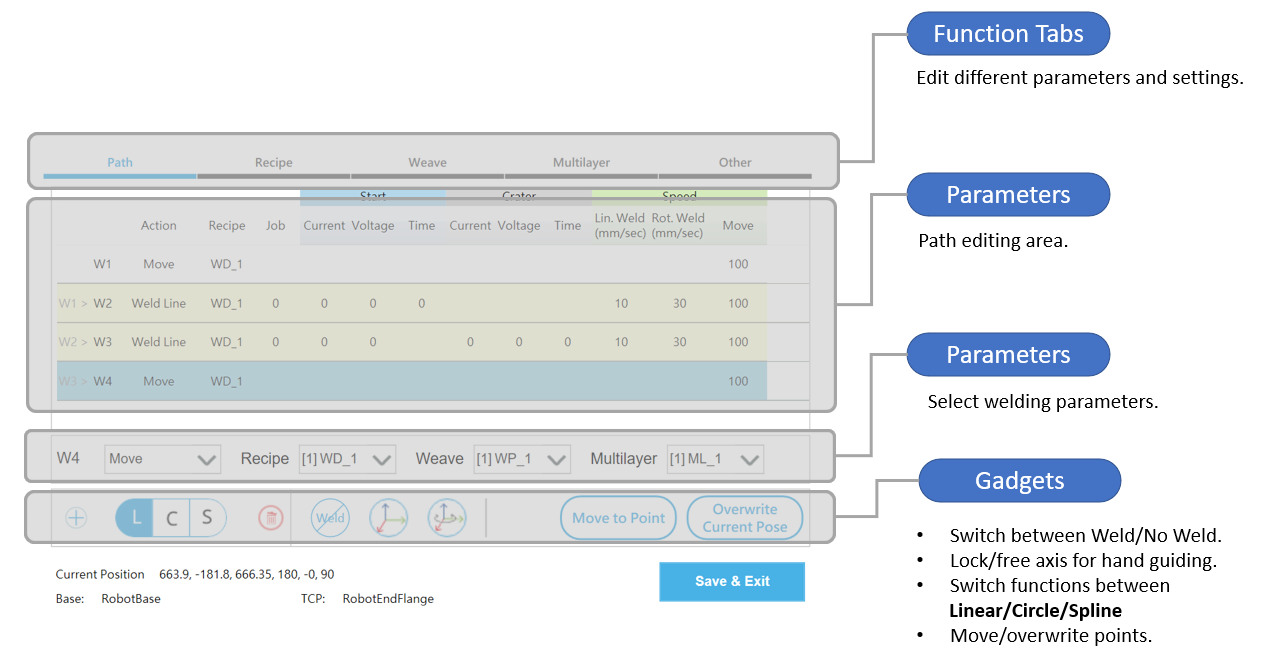
Welding Node – Overview #
Remember to Save on each following step:
When you’re using Move to Point:
- Note that the robot will do line movement even if the points are Weld Arc or Weld Spline.
- Hold the Play button on the stick to move the robot.
Welding Node – Path #
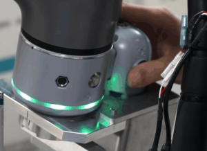
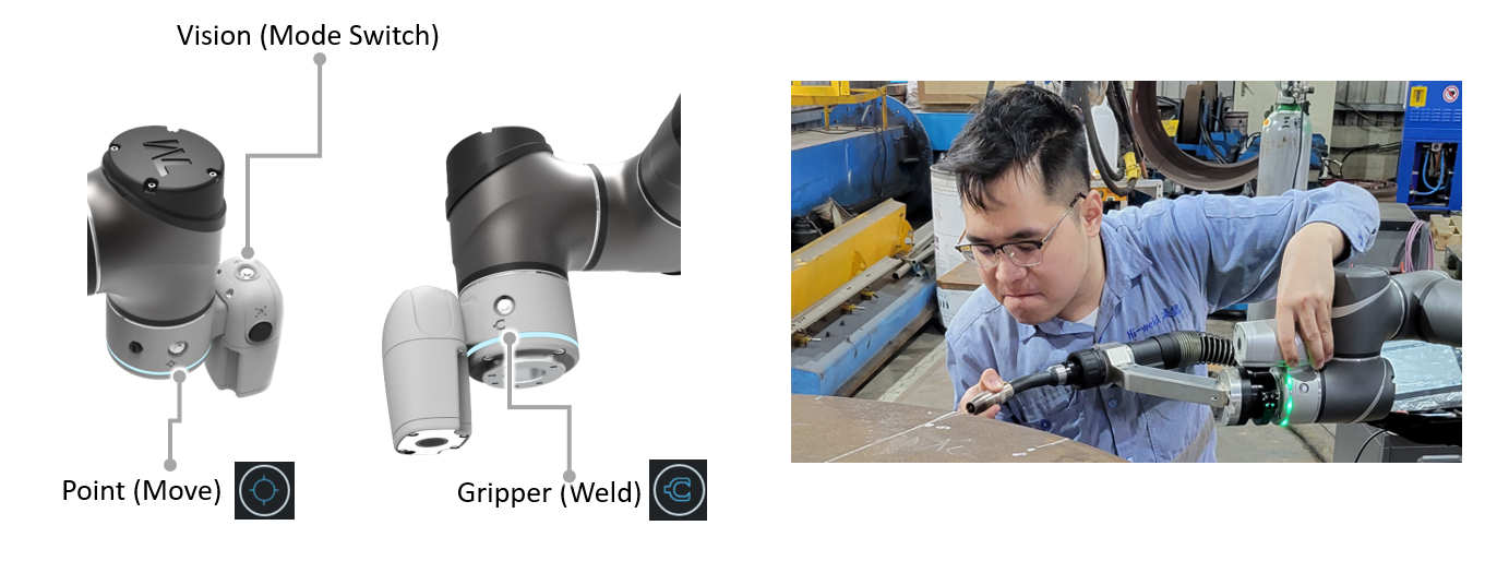
Buttons at Robot Flange #
You can teach Move and Weld with buttons easily. Use Vision Button to swtich mode between Line/Circle/Spline.
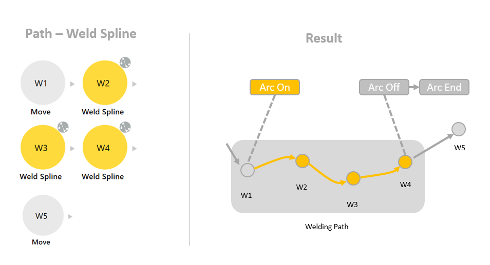
Rules of Path #
Each welding path should start with Move, then Weld Line/Weld Arc/Weld Spline, end with Move. There are some examples:
Weld Line
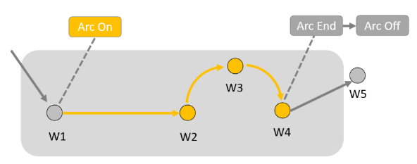
Weld Arc
For a Weld Arc(circular) path, use 2 Weld Arc to create an arc. Each arc path should less than 180 degrees. If you need a whole circle, use the combination of Weld Line + Weld Arc + Weld Arc2 + Weld Arc + Weld Arc2.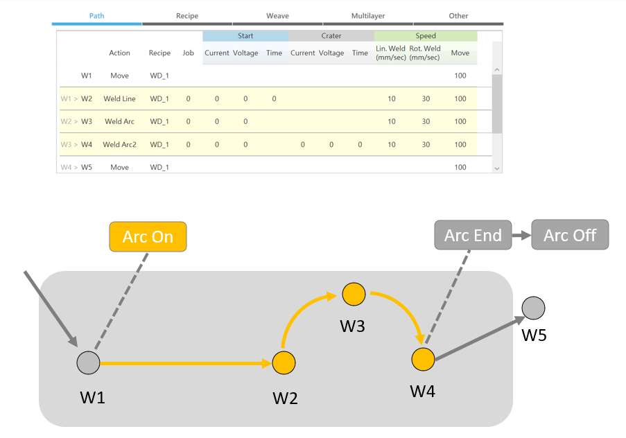
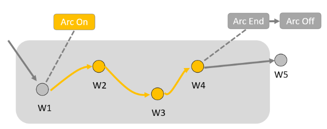
You can use multiple Weld Spline to create a smooth path.

Multilayer
For welding with multilayers, create a Move first then change it to ML MidPoint from Function. Use a pair of ML MidPoint to enclose the welding path.
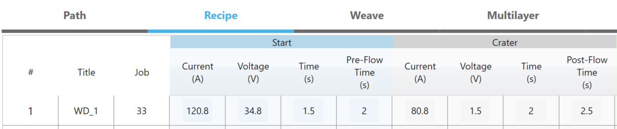
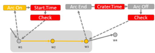
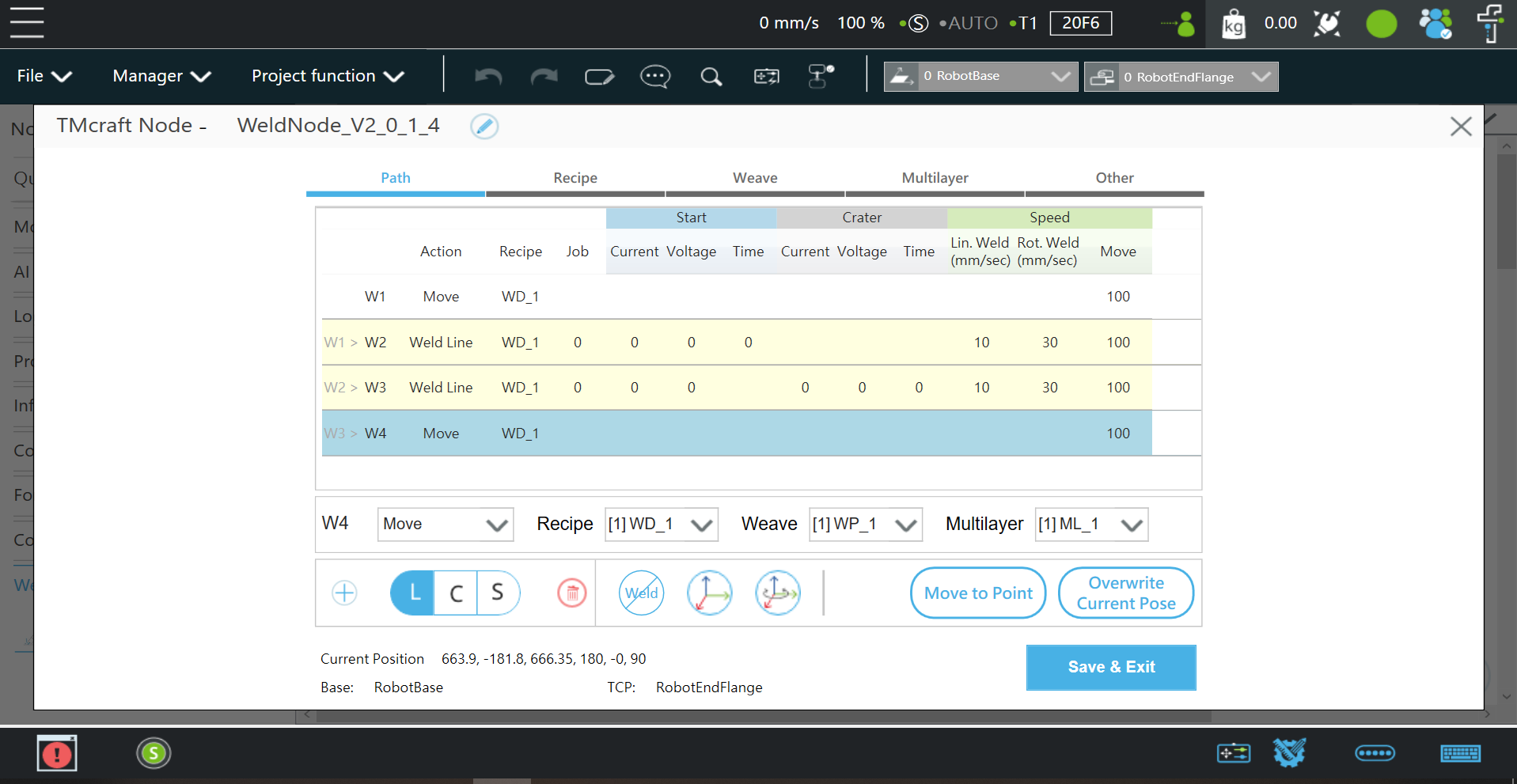
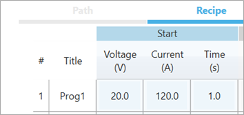
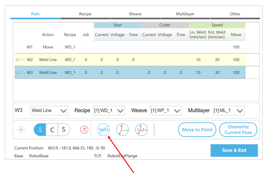
Welding Node – Recipe
In Recipe, you can edit preferred welding parameters.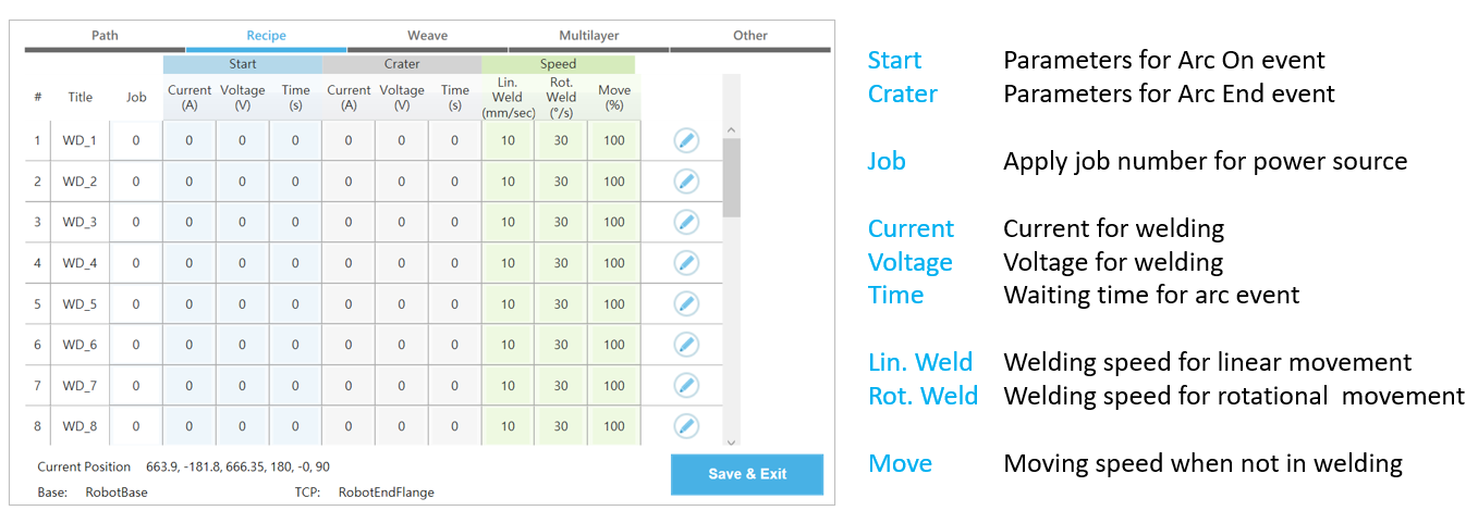
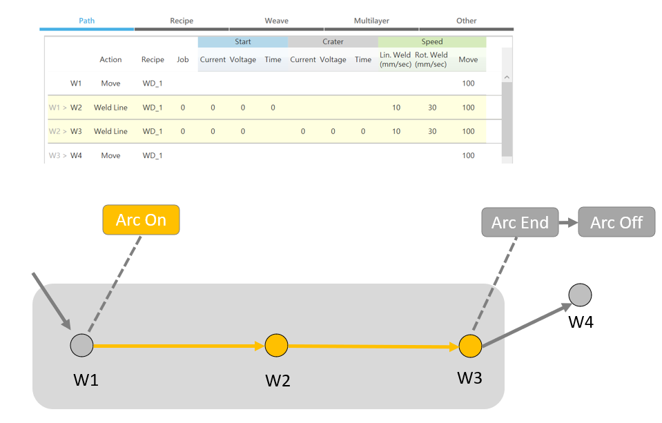
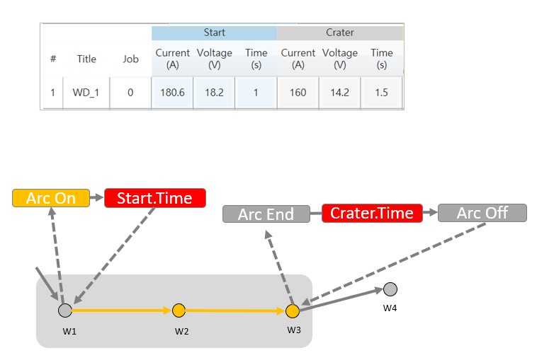
There is an example for setting Start and Crater.
- When it reaches W1, it will trigger the Arc On event(welding) and apply 180.6A and 18.2V then wait for 1 second. Then moves to W2.
- When it reaches W3, it will trigger the Arc End event (end of welding), apply 160A and 14.2V, and then wait for 1.5 seconds. After that, it will trigger the Arc Off event and move to W4.
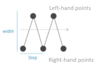
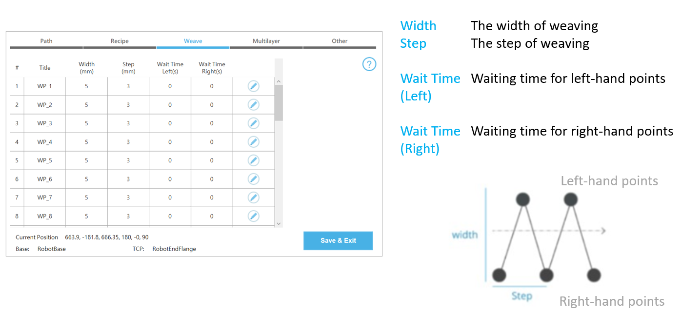
Welding Node – Weave #
In Weave, set the weaving parameters if needed.
There are limitations for Width(0 or greater than 5mm) and Step(0 or greater than 3mm).
The cobot will keep the same welding time no matter the weaving is applied or not. For example, if it takes 10 seconds on a welding path(with the lin. weld speed = 5mm/s) without weaving, then it will take also 10 seconds when the weaving is applied. It will speed up automatically.
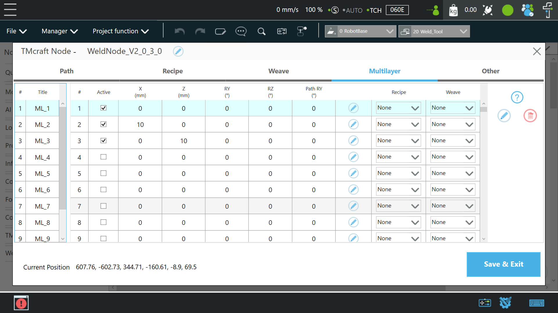
Weldign Node – Multilayer #
In Multilayer, set the parameters for welding with multialyers. Note that at least ONE layer should be actived.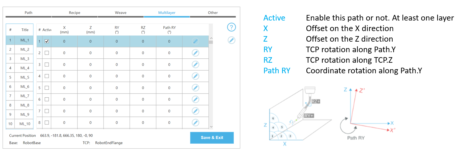
To insert data between layers, select any layer and click the pencil icon on the right side. 
The definition of multilayer coordinate system:
There is an example of using Multilayer:
Example3 : Multilayer Welding for Fillet Weld
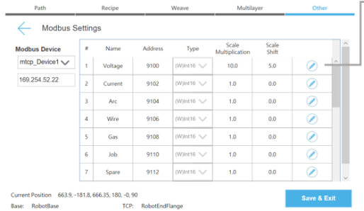
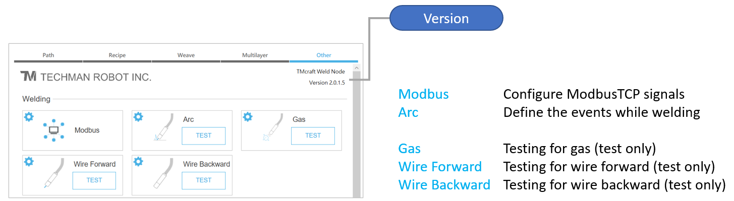
Welding Node – Other #
In Other, set the communication between the robot and the welder.
Configuration data(Recipe/Weave/Multilayer/Other) could be imported/exported to other Welding Node.
Modbus #
In Other, set the communication between robot and welder.
Since Weld Node acts as ModbusTCP Master(Client), configure the robot:
- Navigate to TMflow/Menu/Configuration/Connection, enable Modbus Slave(TCP)
- Navigate to TMflow/Menu/System/Network, enter correspond IP
For example:
- Robot : (IP)192.168.0.100; (Submask)255,255,255,0
- welder : (IP)192.168.0.200; (Submask)255,255,255,0
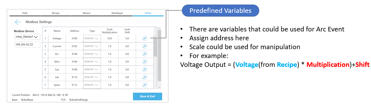
If you’re using ModbusTCP to control welder, you can set different signals here.
There is a function to perform linear adjustment on the output. For example, if we use 20.0V in Recipe, then the result on address 9100 will be (20.0 x 10) + 5 =205(round down to integer). That is, when the robot starts welding, it will send value 205 on address 9100(voltage).
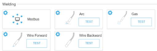
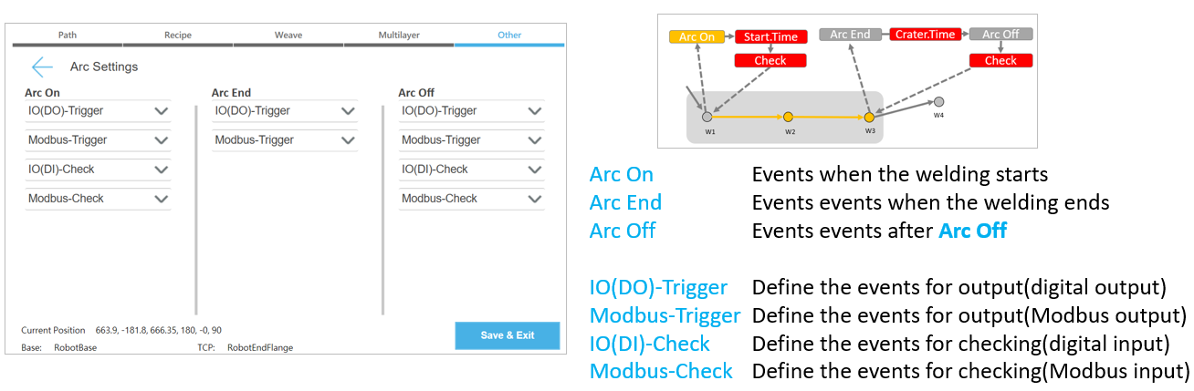
Arc Event #
Arc events will be triggered in sequences automatically, that is, Arc On > Arc End > Arc Off.
You can set arc event for real welding, and no action for simulated welding.
Set I/O or ModbusTCP depend on the communication you need.
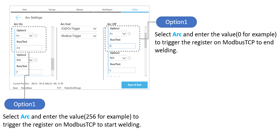
Make sure that Voltage and Current are selected for Arc On event:

Set Option1 in Arc On and Arc Off:
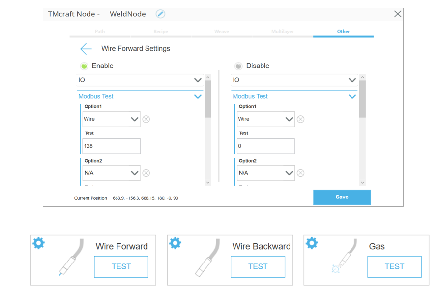
Wire Forward/Wire Backward/Gas #
Do the similar setting to Wire Forward/Wire Backward/Gas. Note that these settings are valid for TEST buttons only and no effect when the program is running.
Unexpected Stop to Cut off Welder. #
Set the signals when robot stops in to cut the power when stop / error occur.
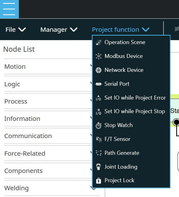
- Project -> Project function -> Set I/O while Project Error
- Project -> Project function -> Set I/O while Project Stop
Note that ModbusTCP commands will stop and could NOT be sent to welder when the robot stopping. There are ways to resolve it:
- Create a TMcraft Service to monitor the I/O status and send cut-off command to welding welder via ModbusTCP. TMcraft Service is running in the background all the time.
- Use I/O to control the output of a welder.
- Use a welding welder that has live-checking mechanism on ModbusTCP. That is, the welder will cut off the output itself when there is no signal change for a while on ModbusTCP.
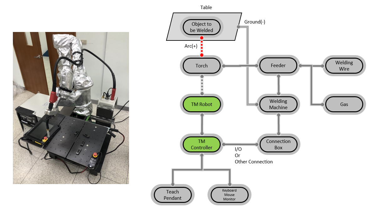
An Example of the Welding Solution #
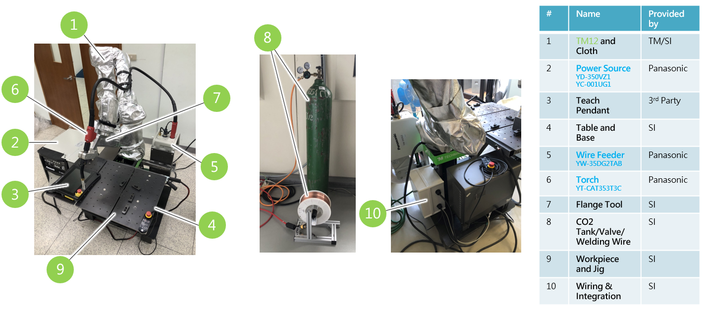
Overview of the system #
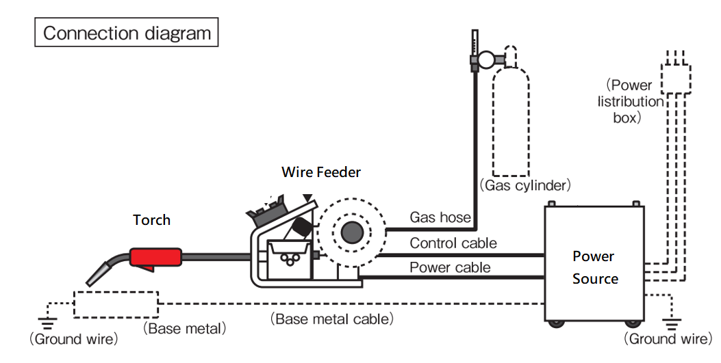
This is an example of leveraging Panasonic power source(general I/O) for arc-welding system . Please consult local Panasonic distributor for more infomation regarding to welding equipments and related manuals.
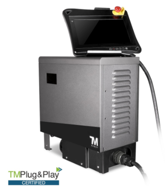
Item#1 Robot and Cover #
Protective cover is suggested to have on robot arm and controller to protect them from spatters, particles. It depends on how harsh the welding environment is.
Products could be found on TM Plug&Play. Since there are slight differences between HW3.2 and HW5.02 for robot arm, please check it with cover manufactures.
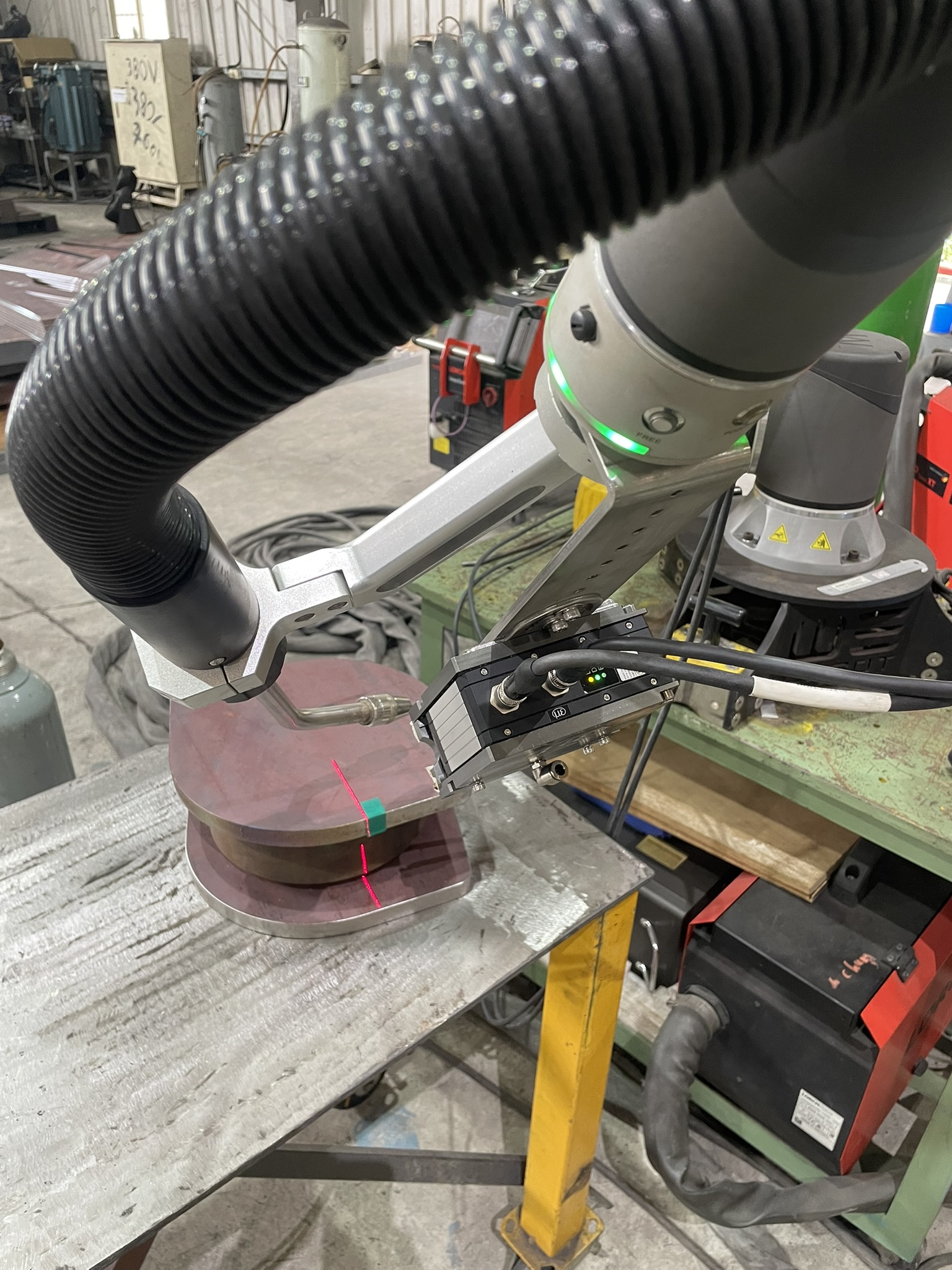
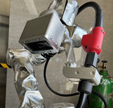
For High-Frquency Power Source(TIG) #
At the moment of welding initiation, the TIG system generates a large amount of noise interference. There are some tips to deal with it:
- Make sure that a good grounding circuit is connected to the base of the cobot and its control box.
- Use a non-conductive material(for example, Bakelite) between the cobot’s flange and the TIG torch.
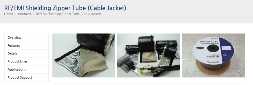
- Use the RF/EMI-proof cable jacket to cover the welding cable. And connect a good grounding to it. Please consult your electrical materials supplier for more information.
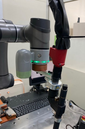
Protection of Vision System
TM provides robot with and without vision camera on flange. If using vision system, it’s necessary to have filter to protect the vision system from direct UV damage in the camera.
There is the reference design for the protection if needed, download link : ![]()
Note that the AUTO UV FILTER MODULE could be found on market easily.

Item#2 Power Source / Item#5 Wire Feeder/ Item#6 Torch #
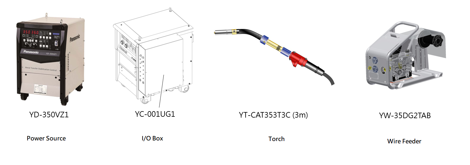
In this example, we used following standard parts from Panasonic:
- Power source YD-350VZ1 and YC-001UG1(I/O interface box)
- Torch YT-CAT353T3C
- Wire Feeder YW-35DG2TAB
Item#3 Teach Pendant #
For TM Cobot with HW5.02, TM Screen is an attachable, optional part that could be attached to TM standard sitck.
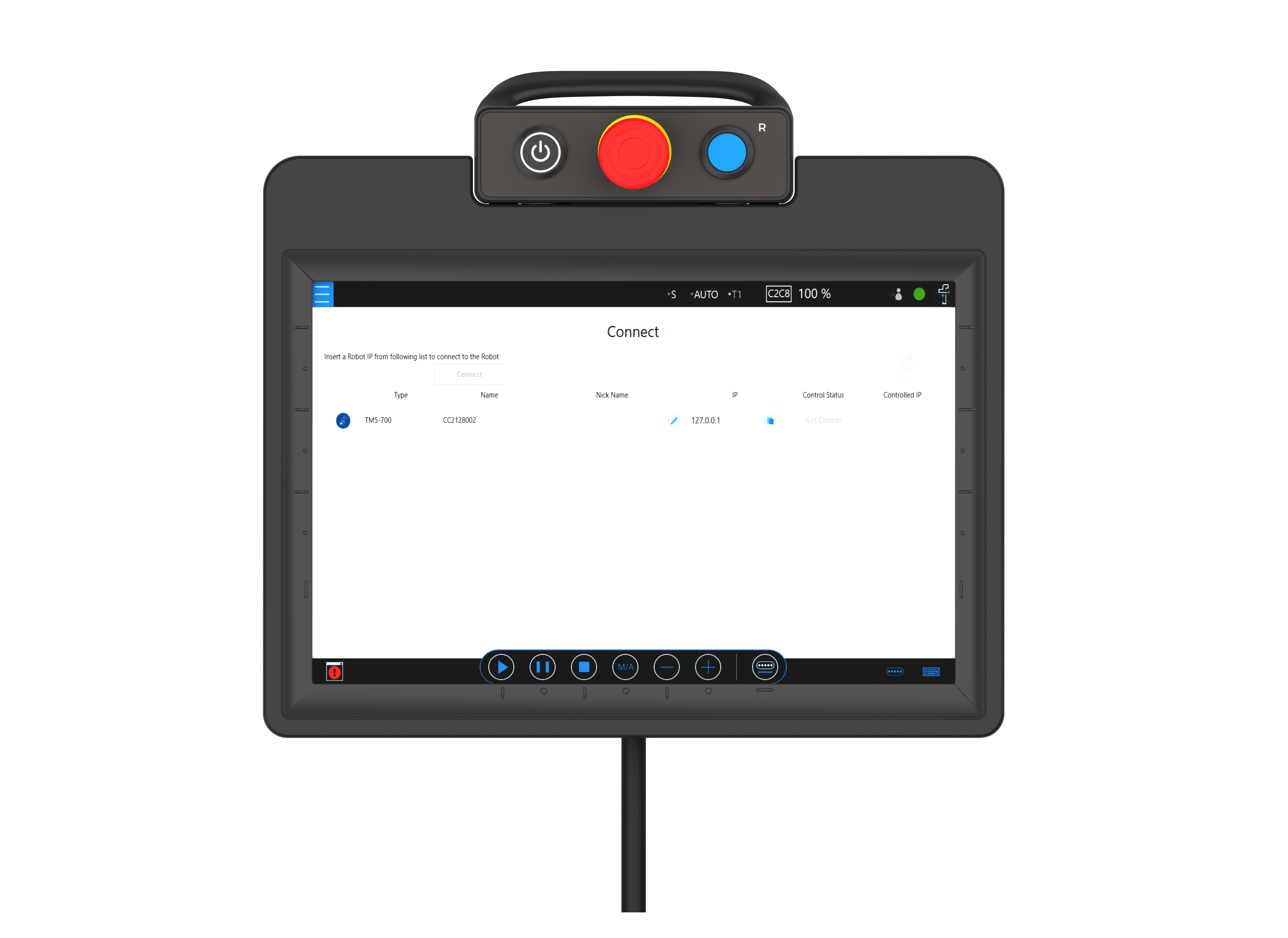
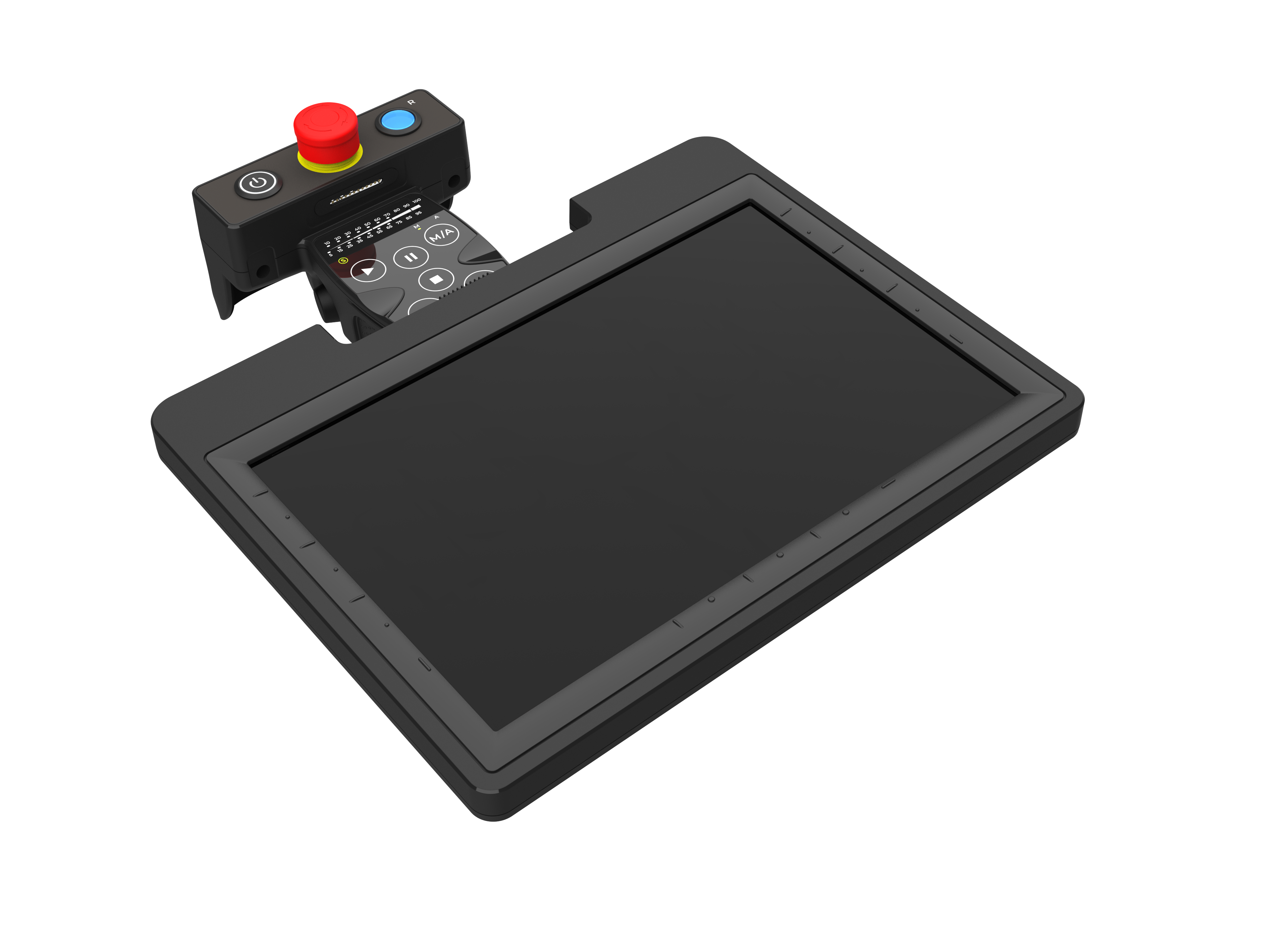
For HW3.2, the optional teach pendant is a 3rd-party item. Please visit TM website -> TMplug&play if you’re interesting in it.
Item#4 Table and Base/ Item#7 Flange Tool / Item#8 CO2 Tank and Welding Wire/ Item#9 Workpiece and Jig #
Those items could be prepared by SI easily.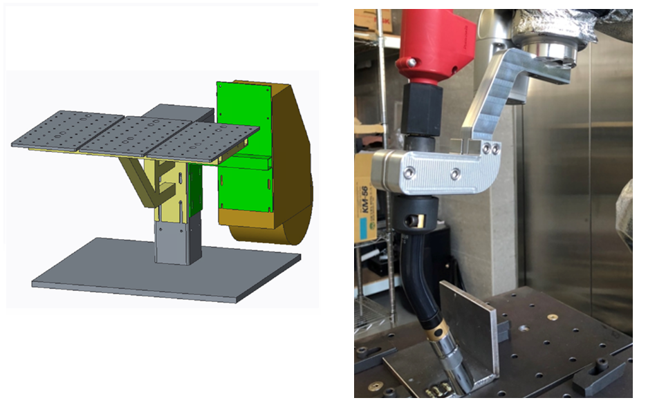
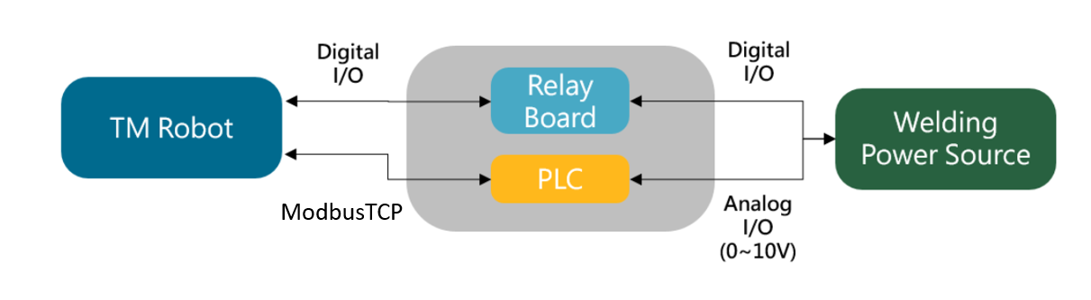
Item#10 Wiring & Integration #
I/O and ModbusTCP #
For I/O connection between TM robot and the welder, there is a junction box needed to be implemented. Key components in the junction box are listed below:
- A PLC with ModbusTCP for analog outputs
- Relay Board – the dry contact to isolate digital signals
- 24V Power – power the PLC
- Terminals – for wiring
PLC could be replaced with external ModbusTCP device:
Related materials:
- How To Add IO Channels With External IO Device Via MODBUS TCP/IP? – for adding external I/O devices on Modbus, refer to Technical Documents
There is the wiring between TM robot and welding power source. For PLC, program the logic to receive commands on Modbus TCP and mapping it to two of analog outputs to control the current and voltage(0V~10V) on the power source.
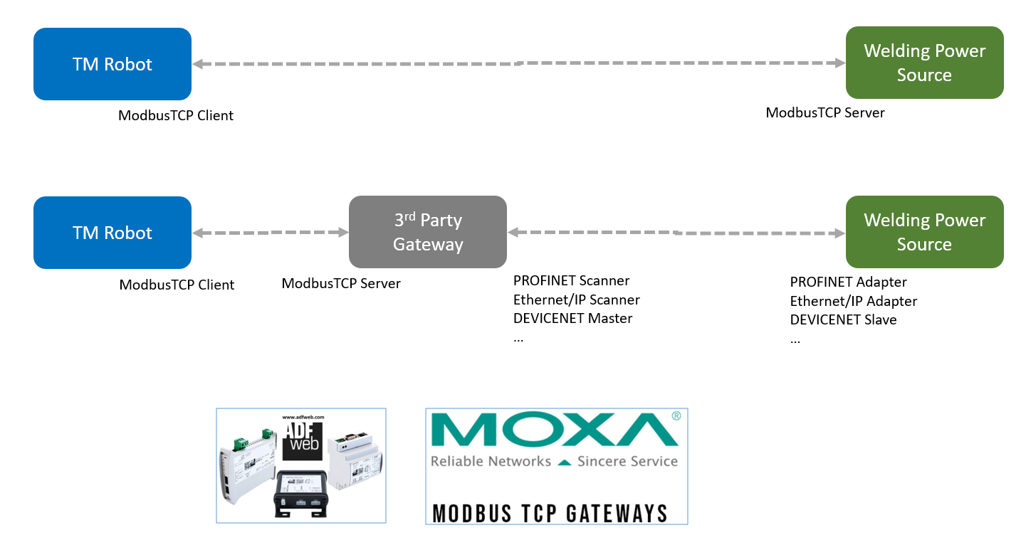
Other Fieldbus #
Most welder equips with fieldbus options, such as Ethernet/IP, PROFINET, ModbusTCP, etc.
Since TM robot provides ModbusTCP as standard, 3rd-party gateway(ADFweb, MOXA for example) could be used for communication on different fieldbus. Please visit their websites for more information.
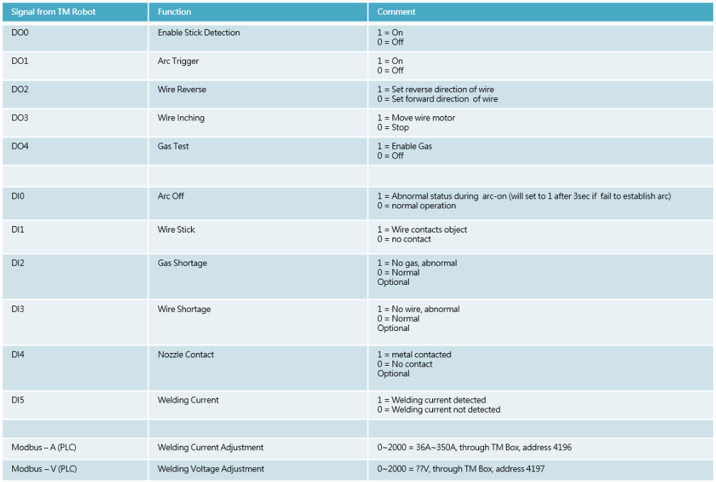
Definition of I/O on TM Robot #
Once the hardware wiring is done, we could control the welder by following I/O definitions on TM robot.
It’s not fixed to the definition below. Modify it to fit your welder.
Check the connection with care before powering up the welding welder and TM robot.
Manual Testing & Programming #
Test the following steps before real welding:
- Gas On(DO4), Wire Inching(DO2/DO3)
- Arc Trigger(DO1)
- Welding Current(DI5)
- Voltage/Current Command
- Teach the welding path
- Test the cut-off function when the robot gets error during welding or stops
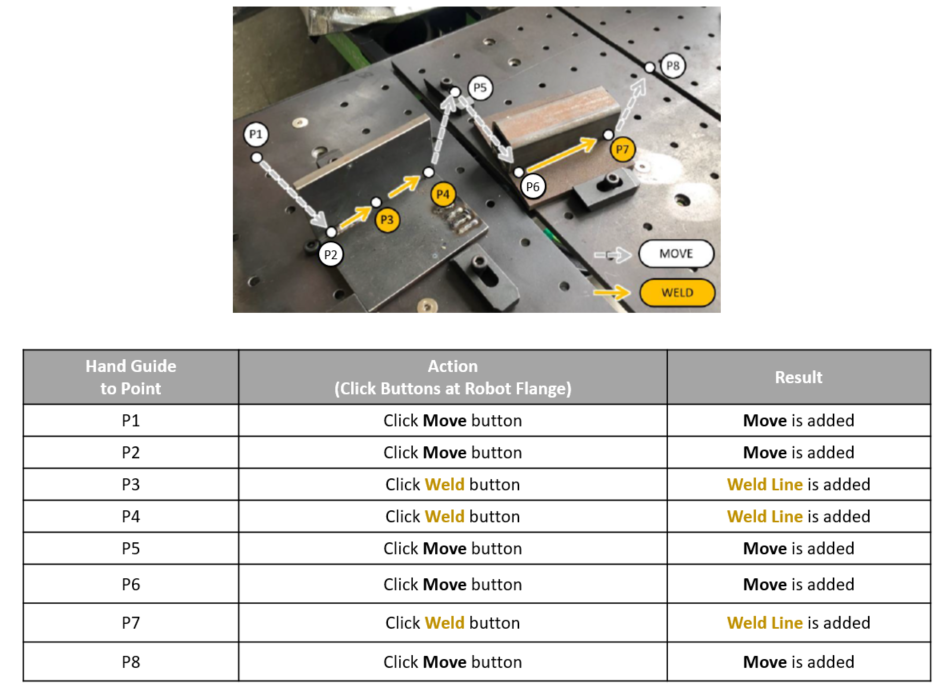
Example1 : Linear Welding #
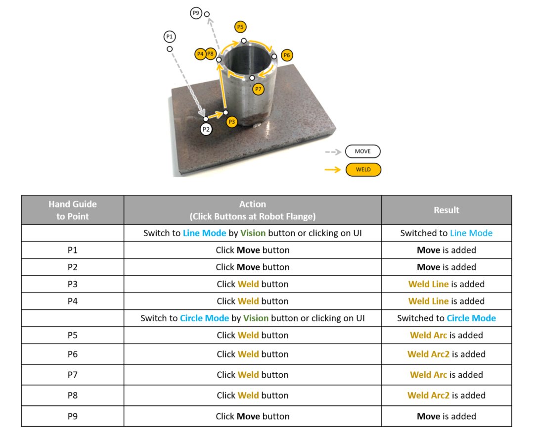
Example2 : Linear and Circular Welding #
Hints
- All setting parameters are stored in that Welding Node. That is, if there are multiple Welding Nodes in one TMflow project, you need to configure them separately.
- Weave and multilayer could be activated simultaneously or independantly.
- Toggle welding event on the button on Welding Node to switch between real and simulated path.
Example3 : Multilayer Welding for Fillet Weld #
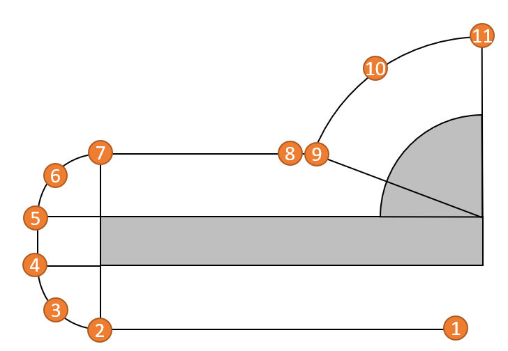
Fillet welds are highly common in welding applications. Below is an example of multilayer settings for a fillet weld.
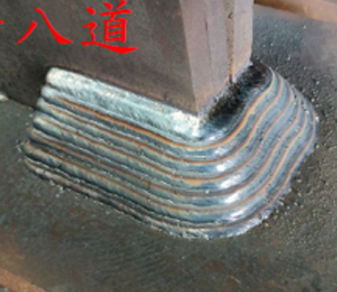
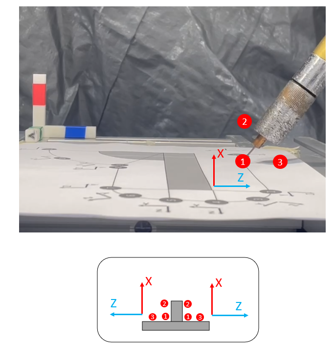
Step1. Explanation of the Goal
Consider a part as below. We are going to apply three welding passes which are marked as RED:
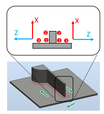
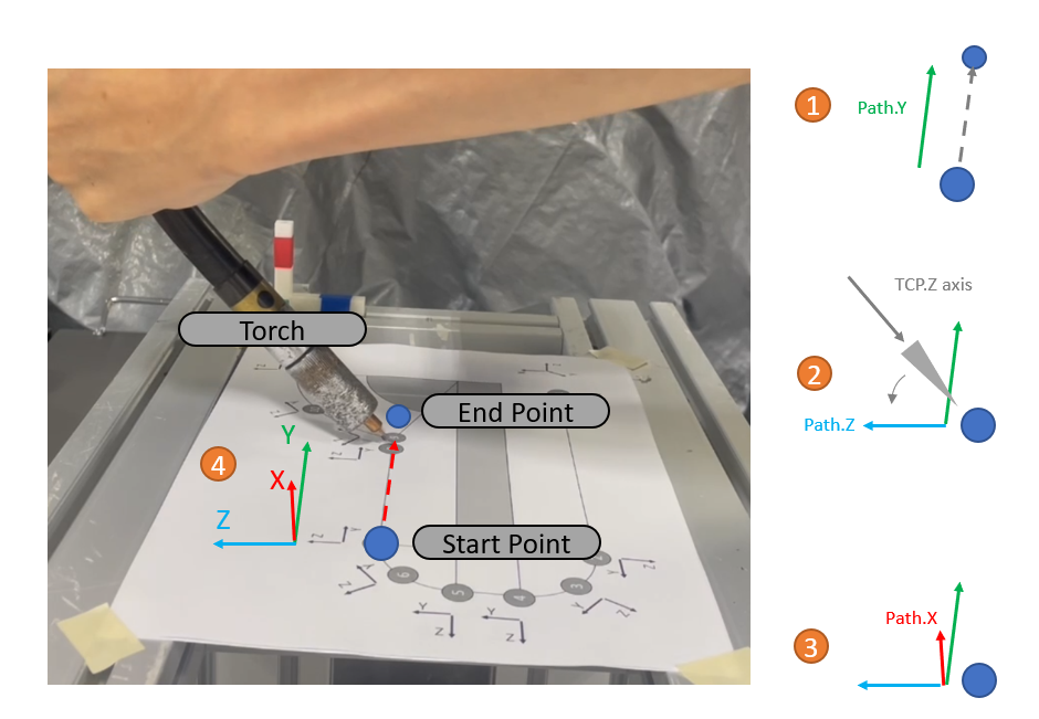
Step2. The Direction of the Path
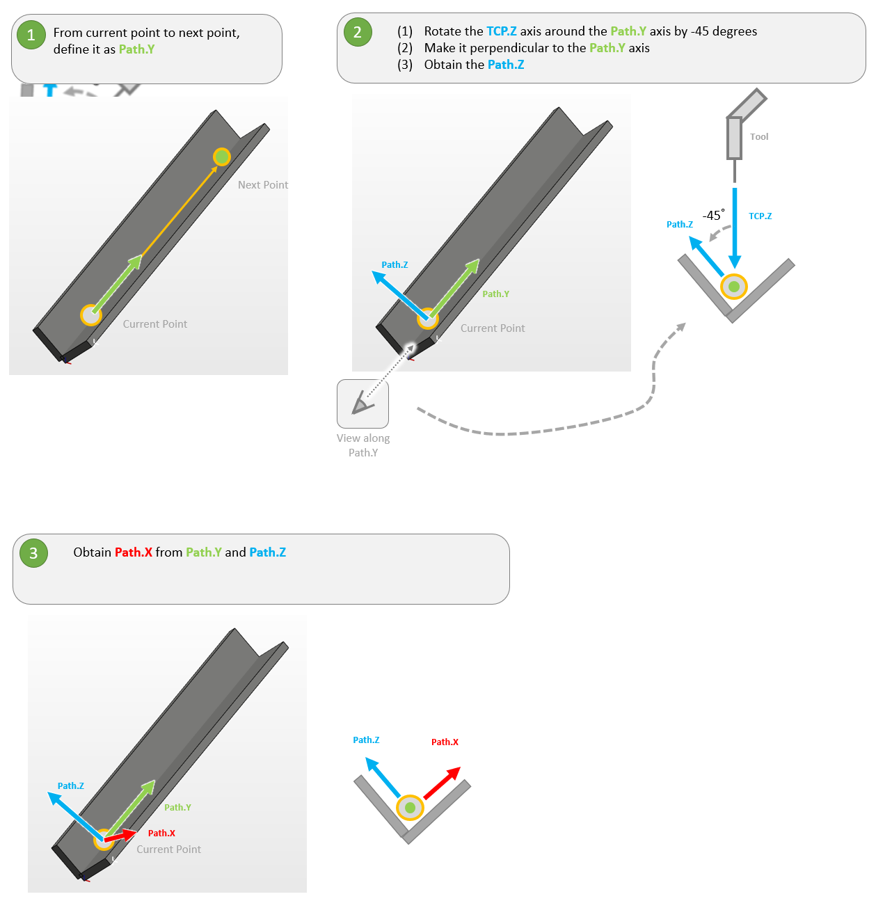
Before teaching the path, we need to know how te define the coordinate of the Path.X/Path.Y.Path.Z axis.
It follows these steps, please refer to the rules:
- Divide the path into several sections(i.e., P1-P2, P2-P3, …)
- For each section, there are a START POINT and an END POINT
- Path.Y is defined by the direction from the START POINT toward END POINT [1]. Path.Y represents the direction of welding motion.
- Looking from the Path Y-direction, rotating the TCP Z-axis 45 degrees counter-clockwise about the Path Y-axis results in Path Z[2]
- The Path.X direction could be obtained by the right hand rule[3]
- Now you have the path coordinate[4] for this section
- Note that the path coordinates are different in different sections
Step3. The Teaching Points
We need to teach P1 to P11 to finish the route(top of view)
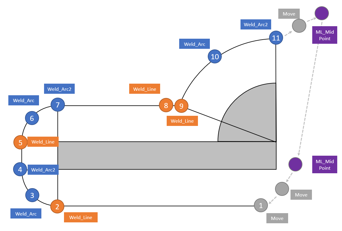
By the procedure above(step2), the coordinates for Multilayer described as below. Note that the coordinates are different in each section.
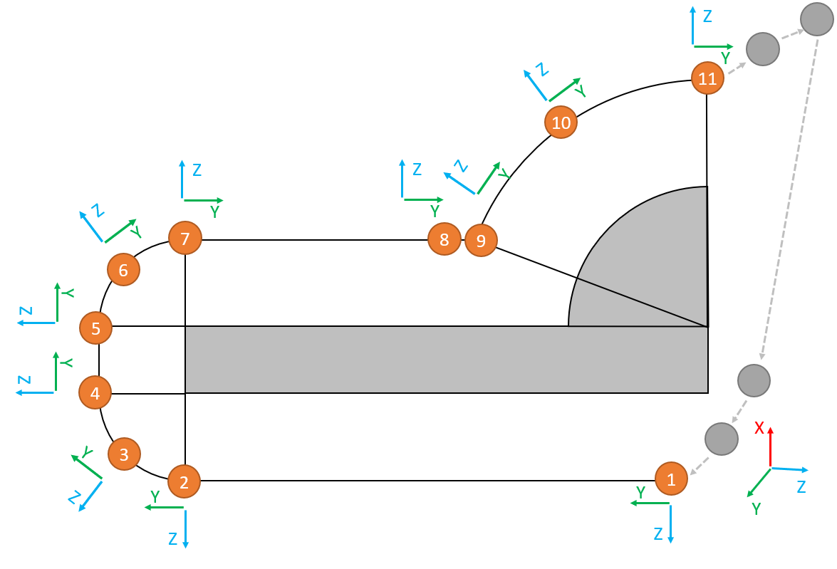
Then we could teach points with different welding functions(move, weld_line, weld_arc, etc.).
Note that ML_Mid Point(02:06 in next video) are needed to create the loop for Multilayer.
The Video for the Teaching Procdure:
Step4. Set up the Parameters for Multilayer
Activate Layer #1~#3 with different offset values as below:
- Layer #1 : no offset
- Layer #2: +10mm in X axis
- Layer #3: +10mm in Z axis
- Set up ML_MidPoint in the Path Page of the Welding Node to create a loop
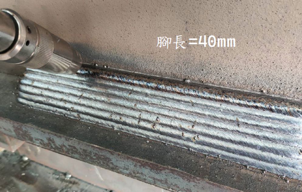
Step5. The Result
The cobot follows the taught points with three layers:
Video in 2X speed:
- Layer #1 0:00 ~ 0:13
- Layer #2 0:17 ~ 0:30
- Layer #3 0:34 ~ 0:48
Real Welding #
Check the safety equipments and environment such as welding mask, fire extinguisher and so on before real welding.
Save and run the TMflow project carefully.
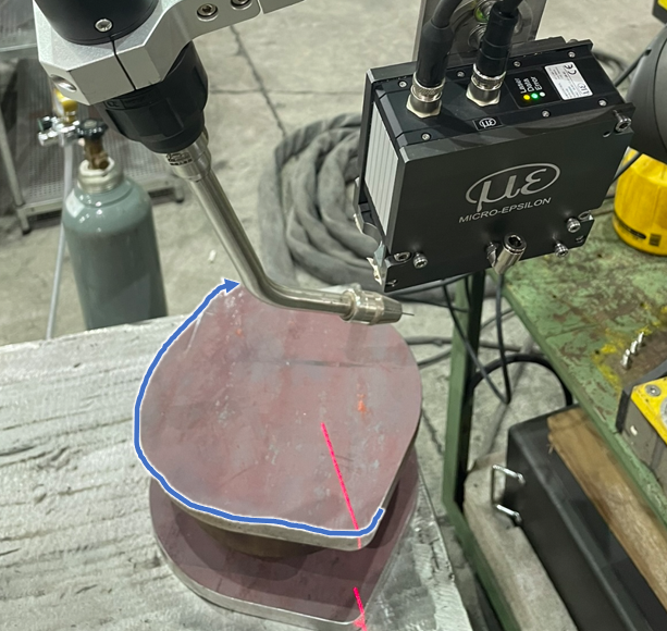
Auto Path Generation with a Laser Profiler #
Benefits #
When dealing with irregular welding paths, this function can be used to automatically generate the welding route, significantly reducing the time required for precise multi-point teaching.
Welding Process Workflow: #
The process follows these steps:
- Manually teach the end point and its approach point.
- Manually teach the start point and its approach point.
- Manually teach the torch angle at the start point.
- Select or set up the scanning parameters.
- Run the project: the robot will move to the end point first, then return to the start point to begin scanning the entire path.
- Once it reaches the end point, the entire path is recorded.
- The cobot will return to the start point and begin welding.
Here is a demonstration:
Application Scenarios: Suitable, Limitation and Under Investigation #
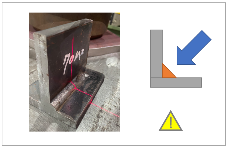
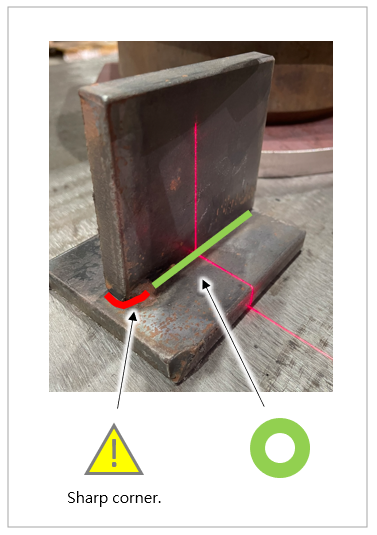
This system works for single and curved path. During scanning, the laser profiler continuously keeps the target centered on the laser line. Therefore, it is essential to ensure that there are no obstacles blocking the path along the movement trajectory.
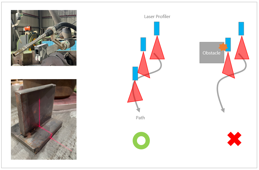
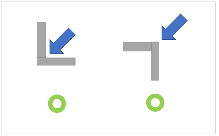
Suitable : Ideal for fillet welds (concave/convex) and butt joints with small gaps
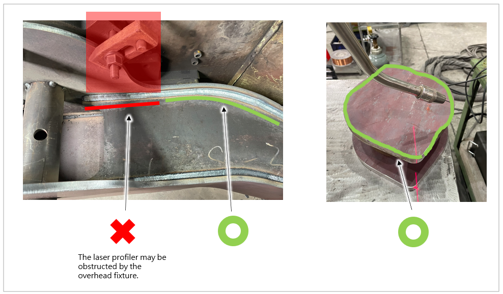
Limitation: Path obstructions:
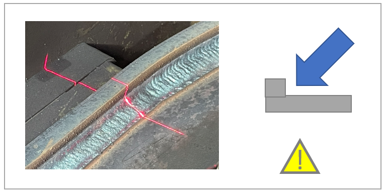
Under Investigation: The current software version has certain limitations regarding low-profile wall welding, pre-existing weld beads or overlapping seams, sharp corners. Our team is actively investigating this, and we expect to implement a fix in a future release.
Hardware Requirements #
TM cobot
- Hardware version: HW5.0
Laser profiler
- Model: micro-EpsilonLLT3012-100(scanCONTROL 3012) Laser Profiler, SMART model.
- Cables: Power cable and Ethernet cable.
- Configuration: A PC to configure the laser profiler.
Fixture
- Mounting: A bracket for mounting the laser profiler to the cobot’s flange.
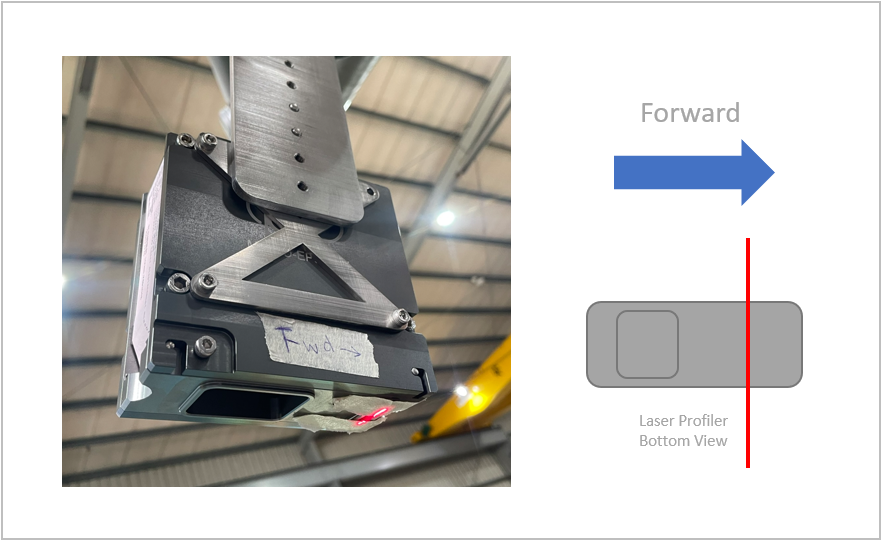
- Alignment: The installed laser line must be positioned close to the wire tip; however, precise parallel or perpendicular alignment is not strictly required.
- Clearance: The scanning range of the laser profiler is 250mm~350mm away from the surface of the profiler. Ensure that the torch does not interfere with the laser profiler’s view of view.
Software Requirements #
TM cobot
- Software version: TMflow 2.22 or later.
- TMcraft Node : WeldNode v2.0.3.1 or later.
- TMcraft Node : WeldThread v2.0.2.5 or later.
- TMcraft Service : WeldService v1.0.3 or later.
- TMcraft Toolbar: scanCONTROL_Toolbar v0.0.1 or later.
- Files and Projects:
-
- TCP file.
- TMflow laser-calibration project.
- TMflow sample project.
-
Laser Profiler Configuration
- Software: scanCONTROL-Configuration-Tools v.6.9.1(please contact micro-Epsilon for more information and manuals).
Installation Procedures #
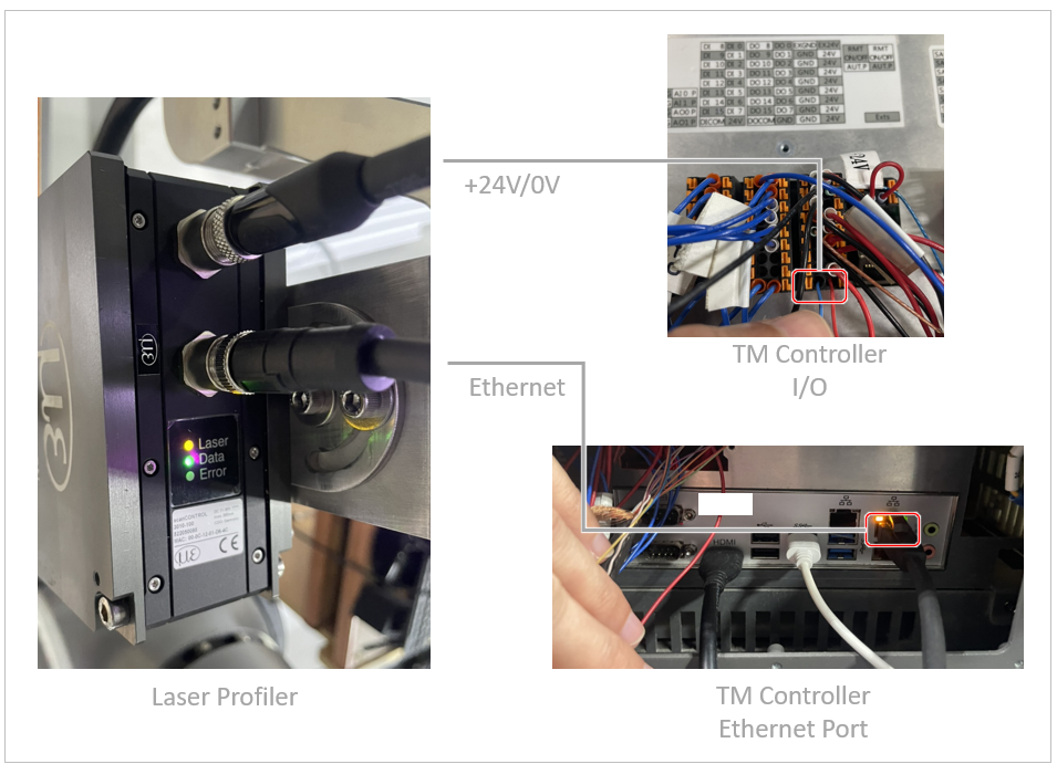
Hardware Setup
- Power Down: Ensure the cobot is turned off before starting the installation.
- Initial PC Connection: Connect the laser profiler’s power and Ethernet cables to a PC for initial configuration.
- Controller Integration: Connect the +24V/0V power leads to the corresponding I/O ports on the cobot controller.
- Controller Integration: Connect the Ethernet cable to the Ethernet port on the cobot controller
- Cable Management: Neatly organize and secure the cables on the cobot arm to prevent them from slipping or being tugged during movement
- Power Up: Turn on the cobot.
Software Configuration – Laser Profile
- Software Installation: Install the scanCONTROL Configuration Tools on your PC.
- Device Connection: Launch the software and establish a connection with the laser profiler.
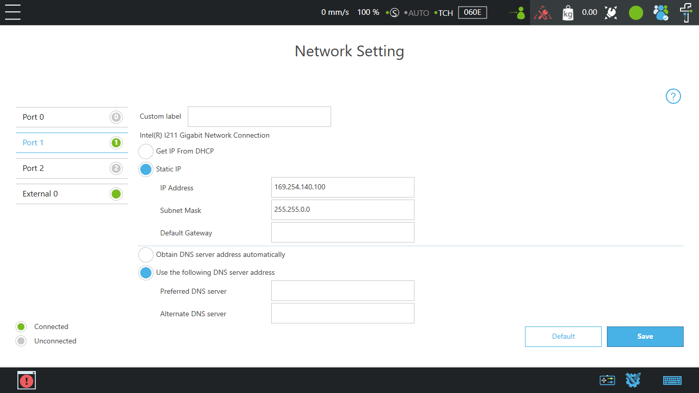
- Network Setup: Navigate to Options > Ethernet Configurator to set the laser profiler’s IP address.
- Use the following default settings:
- IP Address: 169.254.140.108
- Subnet Mask: 255.255.0.0
- Default Gateway: 0.0.0.0
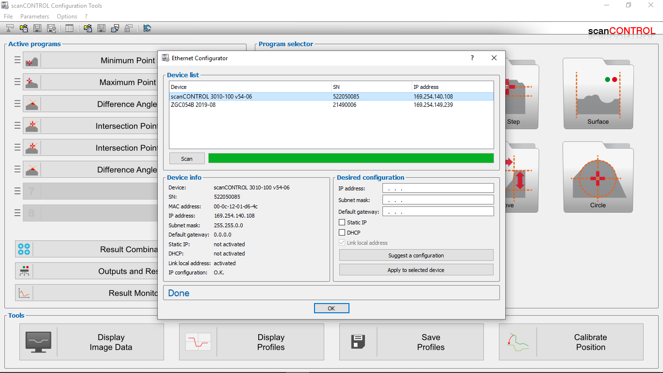
- Finalize: Apply the settings and reboot the laser profiler.
Software Configuration – Cobot
- Import Files: Import files in Software Package Installation with Auto Path Generation
- IP Configuration: Set up the IP of the connected Ethernet port(port1 for example) to the laser profiler:
- IP:169.254.140.100
- Subnet Mask: 255.255.0.0
- Default Gateway: 0.0.0.0
- Hardware Connection: Connect the Ethernet cable between TM cobot(e.g., Port1) and the laser scanner.
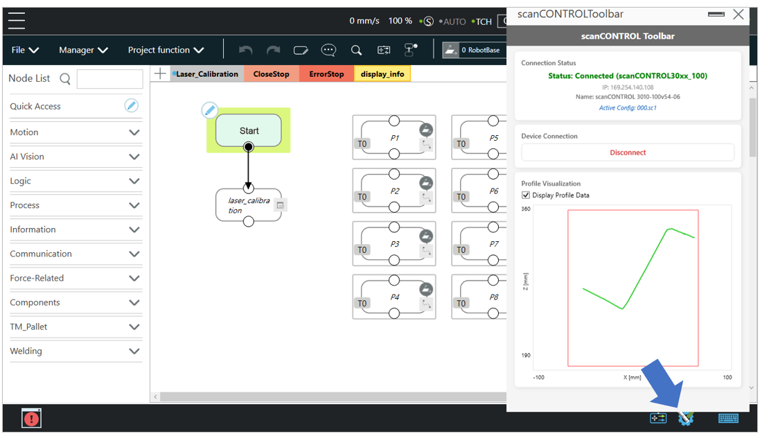
- Verification: Open the scanCONTROL Toolbar to test the connection. The scanned profile should now be visible on the interface.
Calibration Procedures
- Calibration Project Setup: [On the cobot] Open the TMflow Laser-Calibration project.
- Identify Reference Point: Locate a stationary object within the workspace and make a clearly defined mark on a sharp, distinct edge. This will serve as your calibration reference.
- Update P1 to P8 in the project:
-
- For P1 to P8, make sure that the laser line passes through the location of the mark
- P1 : Origiin point
- P2 to P4 : Define linear movements relative to P1.
- P5 to P8 : Define rotational movements centered around the reference mark.
- Here is an example:
-
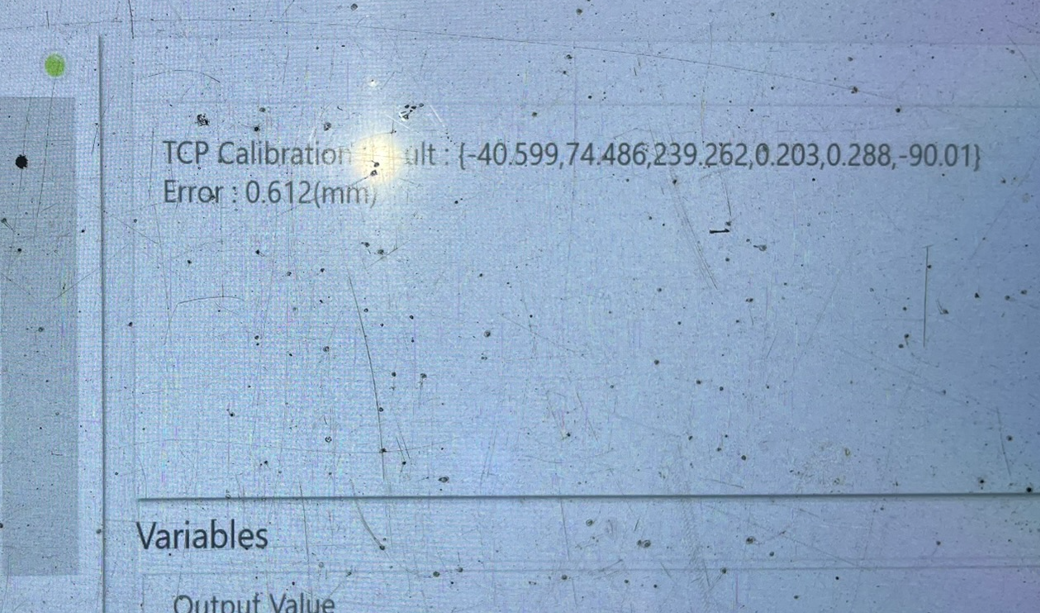
- Run Calibration: Execute the project. Upon completion, the system will display the Calibration Result (Error Value and TCP Value). Ensure the error value is less than 1.0 mm.
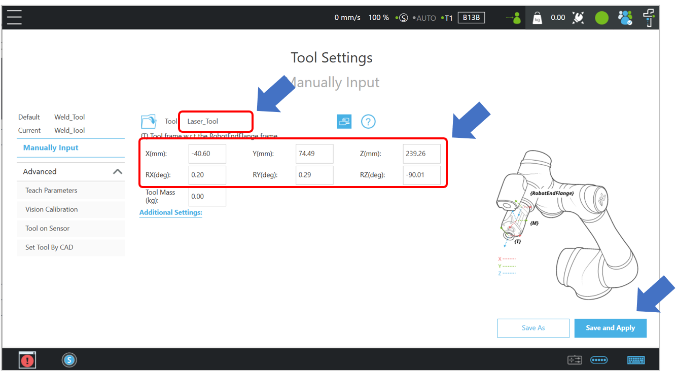
- Apply Tool Data: Go to Menu/Setting/Configuration/Tool Settings/Manually Input, enter the calculated values into the Laser_Tool, then click Save and Apply.
- Teach Torch TCP: Go to Menu/Setting/Configuration/Tool Settings/Advanced/Teach Parameters, Teach the TCP for the tip of your welding torch (e.g., assuming a wire stick-out length of 15 mm). Confirm that the TCP result(error) for the Weld_Tool is less than 1.0 mm.
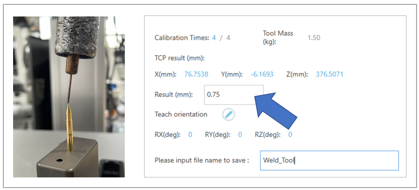
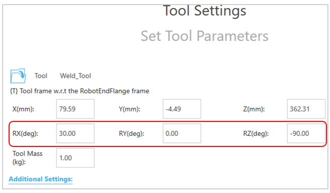
- Then enter the result to the existed TCP Weld_Tool. Note: Weld_Tool is the only TCP compatible with the Auto Path Generation feature. Do not attempt to use other TCP profiles for this function.
- Ensure that the orientation data(Rx/Ry/Rx) are entered correctly with your torch configuration.
Operation Procedures #
-
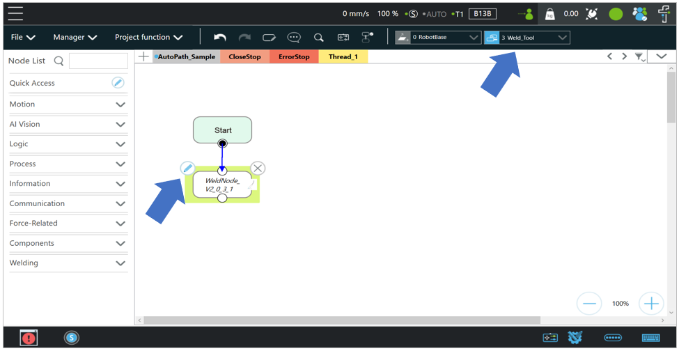
- Open Project: Open the TMflow Project AutoPath_Sample. Make sure that the TCP Weld_Tool is activated. Then edit the WeldNode:
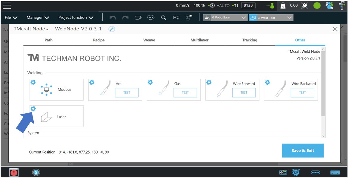
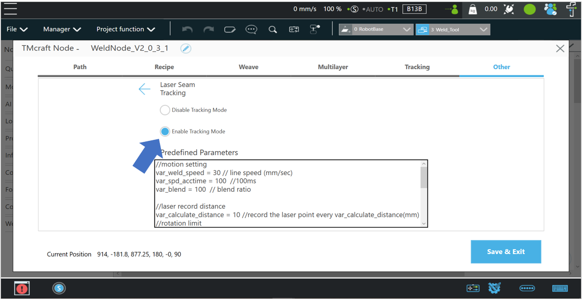
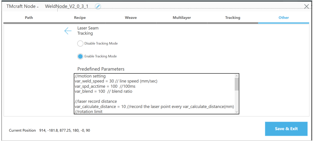
- Configure WeldNode: Go to Other/Laser Setting, enable Tracking Mode:
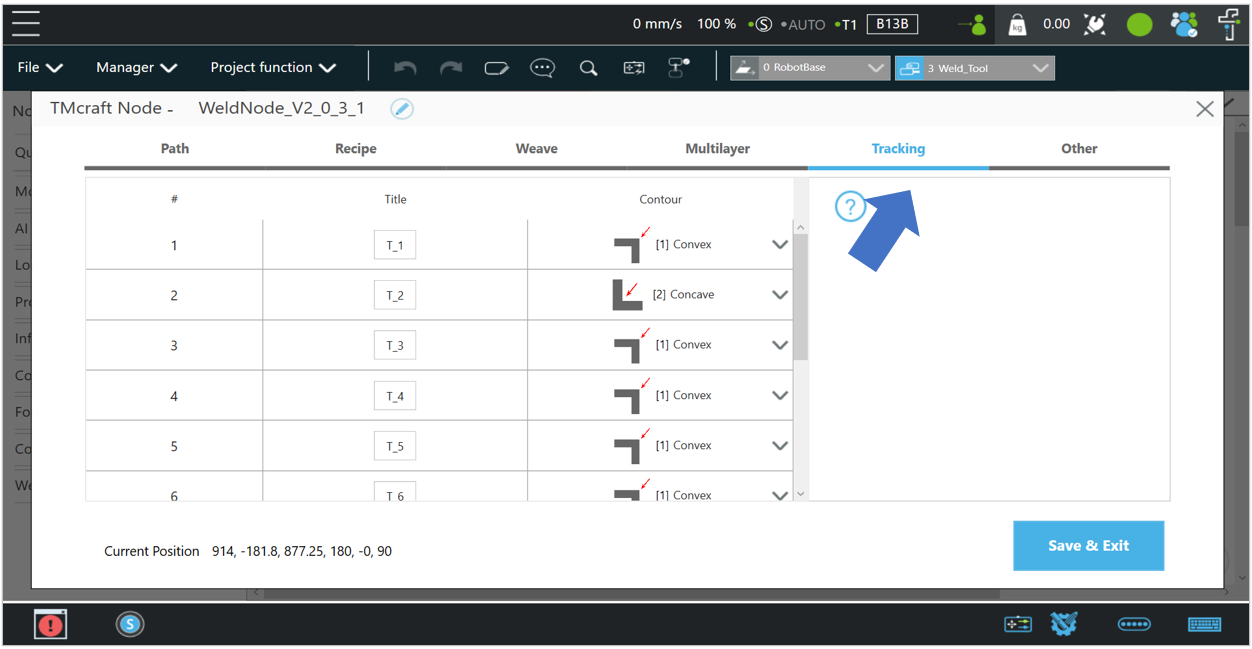
- Define Edge Type: In the Tracking tab, select the appropriate tracking path based on your workpiece geometry: Convex Edge or Concave Edge.
- Configure Scanning Parameters: Navigate to the Path tab to define the scanning direction (Forward or Backward) and specific tracking parameters.
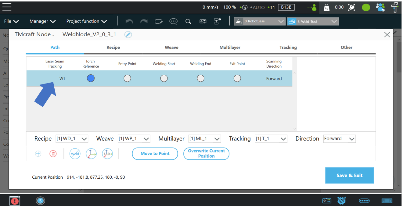
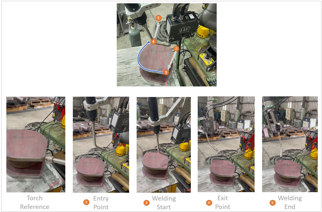
- Teaching the Path Points. To generate an automated path, teach the following sequence of points. Ensure the laser line is clearly visible on the workpiece when locating start and end points:
-
- Torch Reference: Set the desired orientation (angle) of the welding torch at the starting position.
- Entry Point: A safe approach point in the air located before the start of the weld.
- Welding Start: Position the cobot so the laser line precisely identifies the intended start of the weld.
- Welding End: Position the cobot so the laser line precisely identifies the intended end of the weld.
- Exit Point: A safe retract point in the air located after the weld is completed.
- Scanning Direction : Select Forward or Backward to define the sensor’s travel path.
-
- Execution.
-
- Click Save & Exit to store the node settings.
- Run the program to initiate the scanning and automated welding path generation.
- Here is the result:
-
- Open Project: Open the TMflow Project AutoPath_Sample. Make sure that the TCP Weld_Tool is activated. Then edit the WeldNode:
Advanced Parameter Settings #
There are some parameters could be modified if needed:
- Go to Other/Predefined Parametersvar_weld_speed = 30 // Scanning speed//rotation gain value
var_rotate_gain = 0.1 // 0 ~ 1, the smaller the value, the smaller the angle compensation during rotation.//tool offset (if there is an offset between scanned path and the wire tip)
var_x_offset = 0 //(mm) Offset Weld_tool x direction
var_y_offset = 0 //(mm) Offset Weld_tool y direction
var_z_offset = 0 //(mm) Offset Weld_tool z direction
Common Q&A #
Does TM support my welder? #
General I/O (digital + analog) are very common on most welders on the market. Panasonic 350VZ1 in this tutorial is one of them.
It’s not limited to specific brand of welder.
Could I use EtherCAT protocol with my welder? #
No.
TM robot supports following connections:
- General I/O
- Modbus TCP
If the welder uses EtherCAT/PROFINET Scanner/Ethernet/IP Scanner/DeviceNet/CCLink…etc., use a gateway for data relaying.
Does TM support welding type MIG/MAG/CO2/TIG? #
There are different processes related to arc welding such as MIG/MAG/CO2/TIG. It depends on the type of welders, not the robot.
TM robot could control the welder if the connection is supported by TM, no matter it is MIG/MAG/CO2 or TIG, and even laser welder.
Please note that if TIG is using, make sure that the isolation between torch and robot flange is good enough and also the whole grounding should be considered well at the welding feeder side since there will be high frequency noise during TIG welding.
Does TM support weaving(zig-zag)? #
Yes, weaving and multilayer are standard functions.
Does TM support seam tracking? #
No, it’s not supported in current version of Welding Node.
Could I use robot to do thin part welding or Aluminium-based welding? #
Yes if the welder supports. Consult your welding machine vendor for more information.
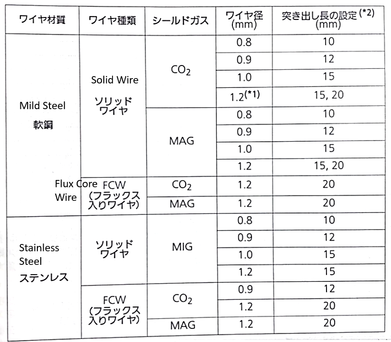
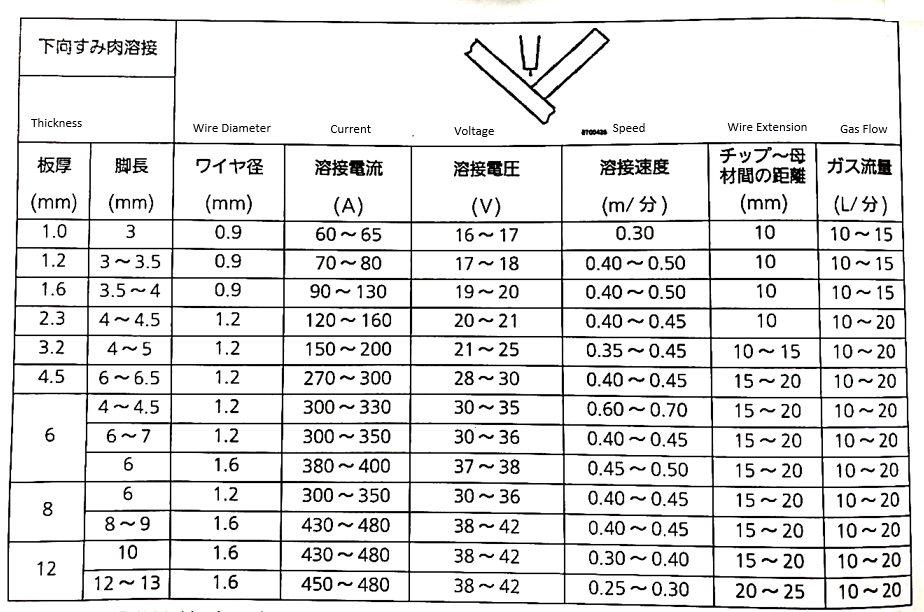
Take Panasonic 350VZ1 welder for example, it supports welding material such as mild steel and stainless steel, from thickness 1~12mm in following welding condition from the manual:
Could I use vision job with Welding Node? #
Yes, functions in TMvision vision job could be used together with Welding Node such as landmark positioning or object positioning.
- First create a Vision Node.
- Set up the vision job.
- Create a Point Node with vision base in step2.
- Connect a Welding Node after the Point Node in step3.
- Step run the Vision Node, make sure that the vision base is updated.
- Switch to the vison base in step5.
- Teach the points in Welding Node.
Suggested welders that compatible with TM? #
It’s not limited to specific welders but there are numbers of welders that are already connected with TM. Please contact to local distributors for more information.
| Maker | Package | Interface with TM |
| Panasonic | YD-350VZ1(welder)
YC-001UG1(I/O interface box) YW-35DG2TAB(feeder) |
I/O |
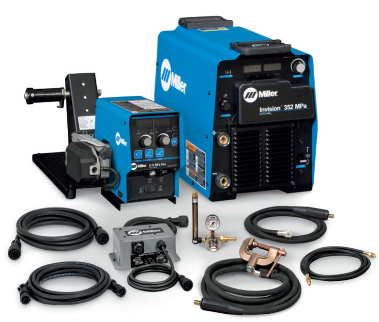
| Miller | Invision MPa Plus Cobot System
Cobot Interface(I/O interface box) S-74 Feeder |
I/O |
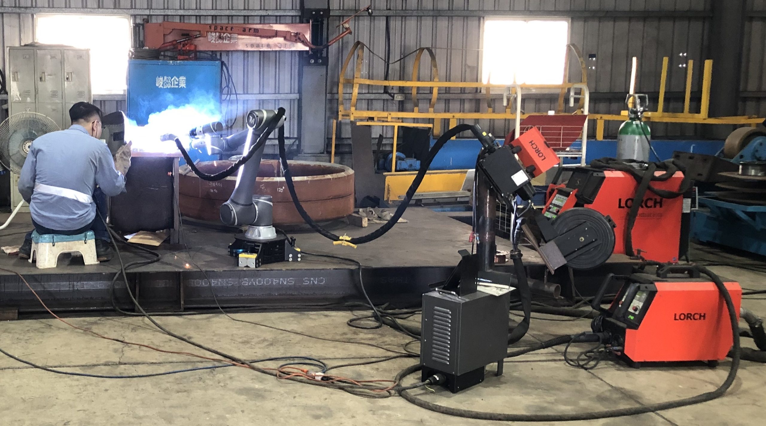
| Lorch | S-series LorchNet-Modbus TCP module Feeder |
I/O
Modbus TCP |
| DAIHEN | Welbee A350P
HC-71D(feeder) |
I/O |
Panasonic
Miller
Lorch
DAIHEN
What is the rotational speed? #
In welding node, we introduced a new parameter Rotational Weld Speed:
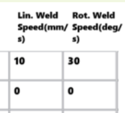
A movement is consisted of linear movement and rotational movement. So we need to define linear speed and rotational speed to tell the robot to move. Then, why rotational speed does not exist before? Because it always has been set to a default value, but we put it in the welding node in case you need to change it.
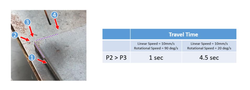
Here is an example to use the rotational speed:
Left: linear speed = 10mm/s, rotational speed = 20 deg/s
Right: linear speed = 10mm/s, rotational speed = 90 deg/s
When it move from P2 to P3, it is a simple rotational movement(that is, no linear movement), so linear speed does not affect the result, but rotational speed does! So you can modify rotational speed to adjust the travel time or speed at the corner, that will affect the welding result.
There are more examples when combine linear and rotational movement: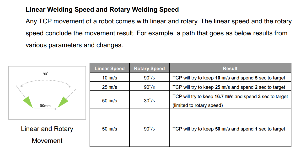
The Cobot Is Interfered by The TIG Machine. #
The strong noise will interfered the cobot at the ignition state of TIG welding, and the cobot might have a red-light error due to the safety mechanism for the motor communication. Please refer to the chapter for the countermeasure.
An Example of the Welding Solution / For High-Frquency Power Source(TIG)


