Examples are valid for
TMflow Software version: 1.88 or 2.14 above
TM Robot Hardware version: HW 3.2 or above
Window version: Window 10 or above
Other specific requirements:
- Vision Demo Kit
- TMflow Project
- Vision Demo Kit project for TMflow 1.88: DemoKit 1.88

- Vision Demo Kit project for TMflow 2.14:
- v1: DemoKit 2.14 v1
- v2: DemoKit 2.14 v2
- Vision Demo Kit project for TMflow 2.16:
- v1: DemoKit 2.16 v1
- v2: DemoKit 2.16 v2
- Checking DH calibration project: RobotAccuracyInspection
- Vision Demo Kit project for TMflow 1.88: DemoKit 1.88
Warning: Please download the corresponding project according to the Vision Demo Kit Plug-in Plate version.
Notice:
-
-
- TMflow Project and TCP should be imported together. For details, see Import a Project and TCP
- Don’t modify the project name before importing the project
-
Note that older or newer software versions may have different results.
Introduction #
Overview of Vision Demo Kit #
- Purpose: To demonstrate the benefits of Techman Robot’s products to our customers and instruct them to use Vision Demo Kit.
- Direction: TM AI and TM Vision
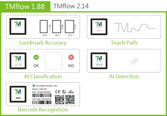
TMflow 1.88 above
-
- Landmark Accuracy
- Demonstrate precise landmark positioning and manipulate the end effector to penetrate holes, with the tolerance being as low as ± 0.1 mm.
- Teach Path
- Teach the robot to remember the movement trajectory and move along the marked lines of the trajectory.
- AI Classification
- Use AI to recognize defective workpieces.
- AI Detection
- Use AI to detect the number and location of all dice.
- Barcode Recognition
- Read various types of barcodes on product labels.
- Landmark Accuracy
TM flow 2.14 above
-
- AI Anomaly Detection
- Use AI to identify scratches on textured surfaces to mark their status “NG” or “OK.”
- AI OCR2
- Support the majority of commercially available fonts.
- AI Anomaly Detection
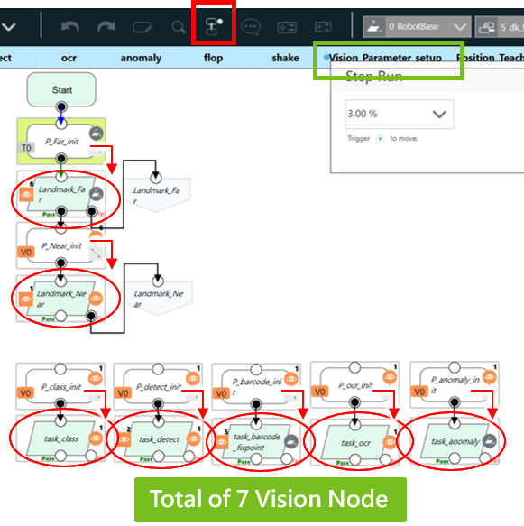
How to Showcase the Vision Demo Kit #
- Of the four sides of the Vision Demo Kit box, one side is a magnetic plug-in plate and the other three sides can be replaced with any task plate.

- Place the Task Plate of your choice where it faces the camera, and TMflow will automatically identify the type of the task and execute the task.
- After any of the aforementioned seven tasks is completed, flip the Vision Demo Kit Box and TMflow will switch to the next task.
- For Landmark Accuracy and Teach Path tasks, the Vision Demo Kit Box can be placed on the 45º stand for demo.
Operation Procedure #
1. First Landmark positioning
Find the Landmark on the Vision Demo Kit Box 20 cm away from the camera.
2. Second Landmark positioning

Precisely identify the Landmark 10 cm away from the camera.
3. Task classification
Classify patterns of the custom landmark.
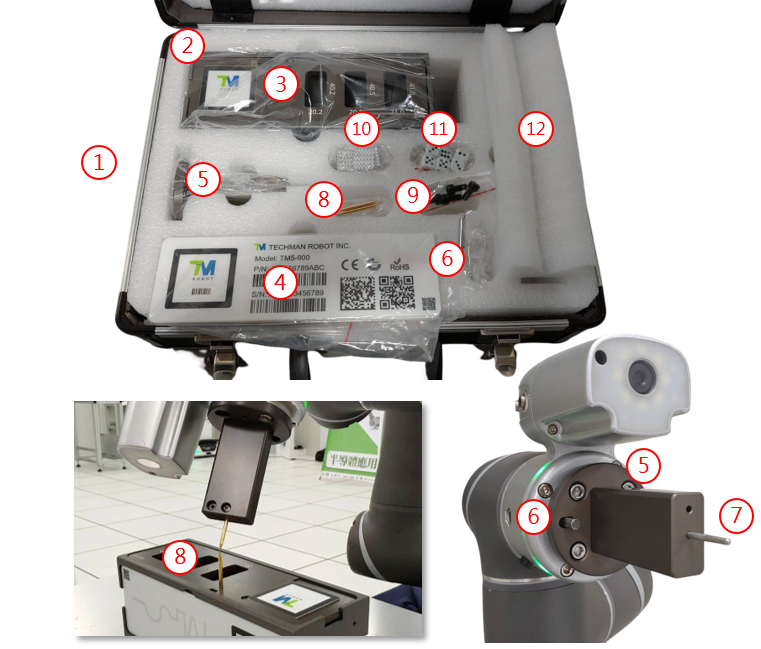
Vision Demo Kit Tasks #
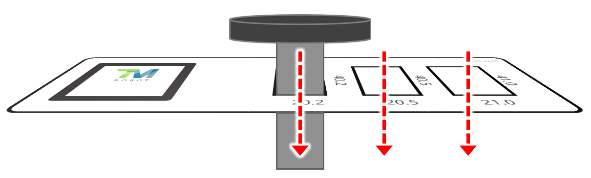
Vision Demo Kit: Landmark Accuracy
#
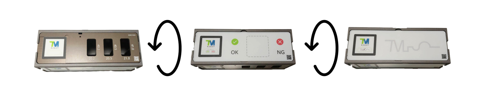
- Demonstrate precise positioning and manipulate the Vision Demo Kit Tool (the end effector) to penetrate holes, with the tolerance being as low as ±0.1 mm.
- There are 3 holes of different sizes—with a tolerance of ±0.1 mm, ±0.25 mm, and ±0.5 mm, respectively.
- Vision Demo Kit Tool size: 40 mm in length, 20 mm in width
- Landmark positioning allows the Vision Demo Kit to be placed in any pose and any position within the camera’s field of view.

Vision Demo Kit: Teach Path
#
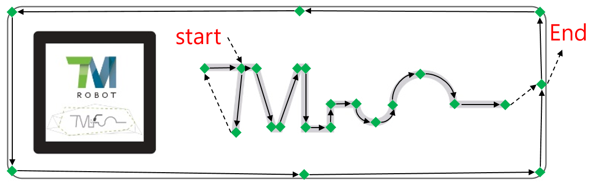
- Teach the robot to remember the movement trajectory and move along the marked lines of the trajectory.
- Keep a constant speed throughout the entire trajectory by blending and velocity settings.
- For dispensing and welding applications.

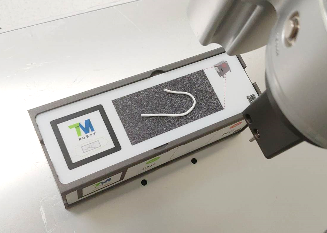
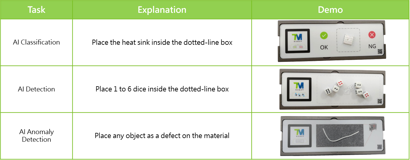
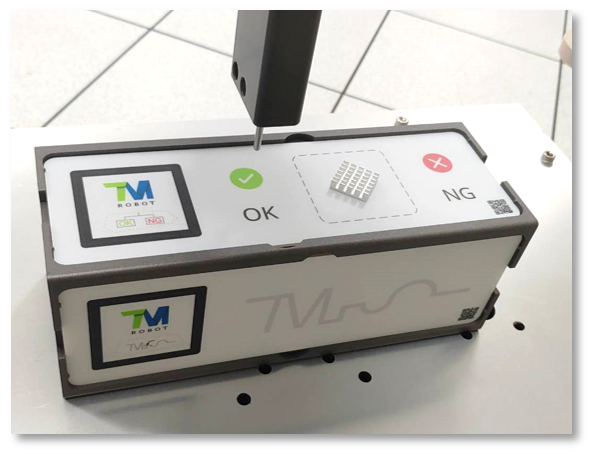
Vision Demo Kit: AI Classification
#

- Identify defective workpieces using AI.
- Classify the heat sinks as normal (OK) or defective (NG).
- A heat sink can be placed randomly in the dotted-line box.
- Vision Demo Kit Tool will point to the classification result.

Vision Demo Kit: AI Detection
#
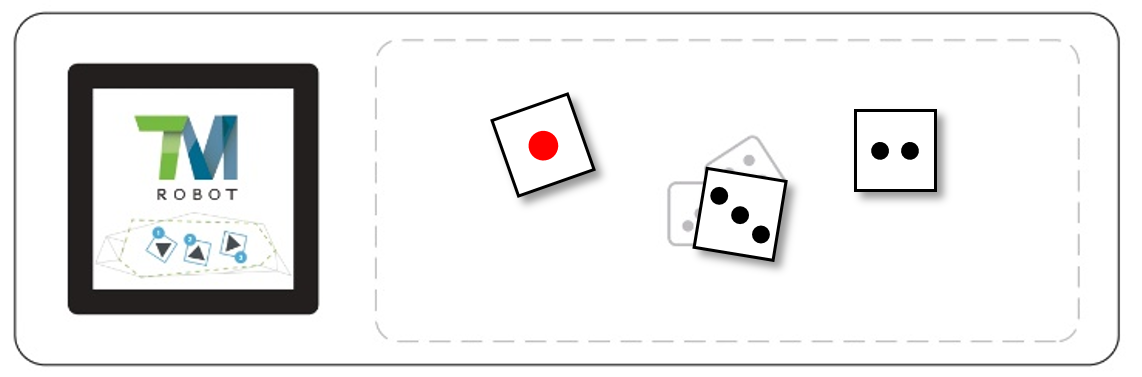
- Use AI to detect the number and location of all dice.
- The task plate accommodates 1 to 6 dices.
- Point to each dice in sequence and display its digit.
- Display the number the number on the upper surface of a dice and the sum of the dices.

Vision Demo Kit: Barcode Recognition
#

- Read various different types of barcodes on product labels.
- Use OCR to recognize a set of digits above a barcode and check it against the barcode.
- Before barcode recognition is performed, the the Vision Demo Kit Box is photographed from all sides (this is similar to how AOI inspection is executed).

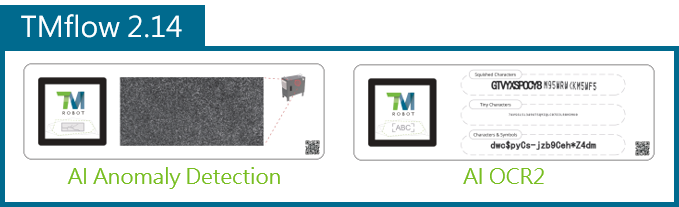
Vision Demo Kit: Anomaly Detection
#
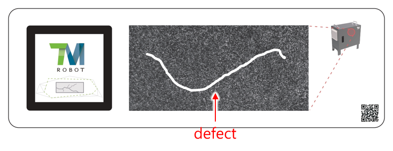
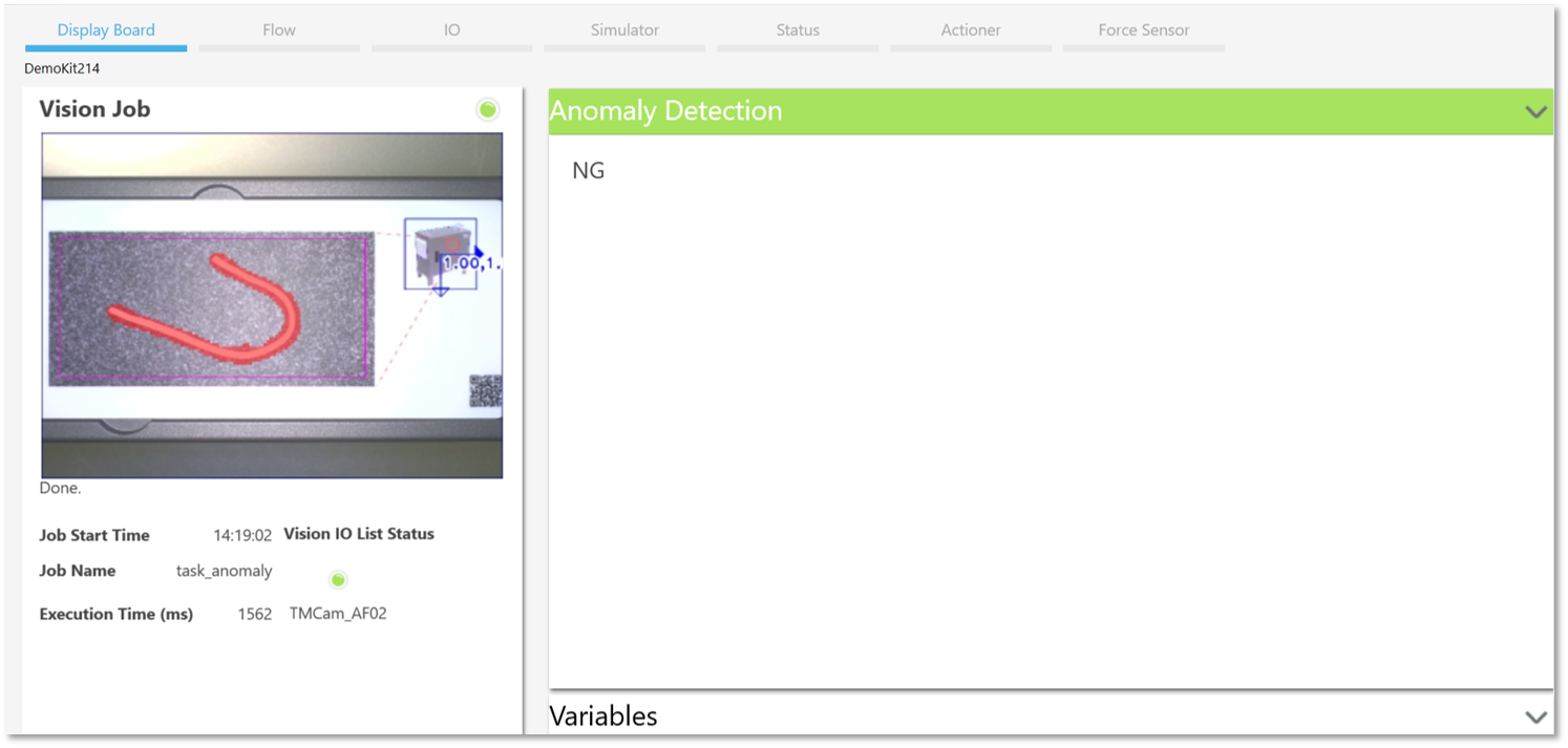
- Use AI to identify scratches on textured surfaces to mark their status “NG” or “OK.”
- Unlike classification, anomaly detection needs only OK samples and a few or even no NG samples.
- Applicable when it is difficult to collect NG samples.

Vision Demo Kit: OCR2
#
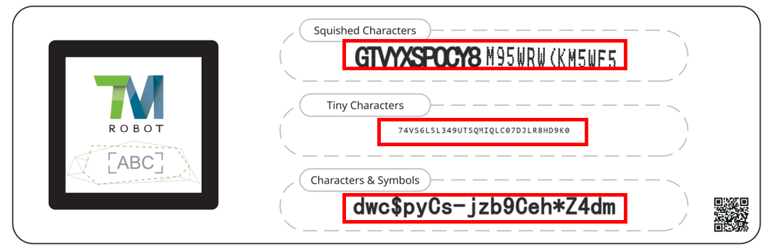
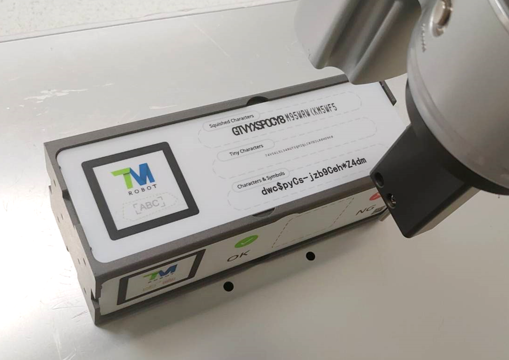
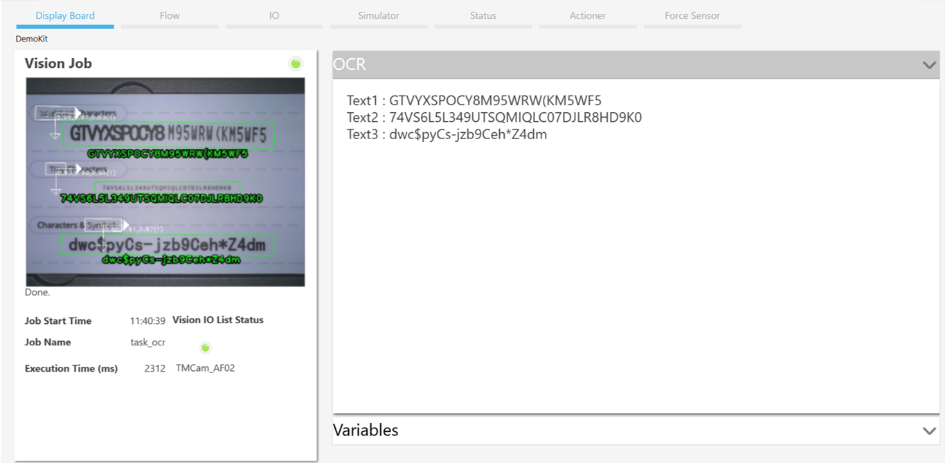
- AI OCR supports the majority of commercially available fonts.
- Powerful character recognition capabilities:
- Recognize characters even if they are squished.
- Recognize tiny characters.
- Support upper and lower-case alphabets, numerals, and symbols.

Environmental Setup
#
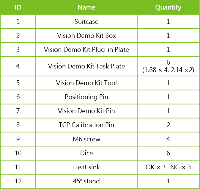
Vision Demo Kit contents
#
Requirement #
- Hardware: HW 3.2 or above
TM Calibration Board - Software: TMflow 1.88 or above ( for Anomaly Detection or OCR2, use TMflow 2.14 or above)
- Window: Window 10 or above
- Other equipment: TM calibration plate
- DH calibration: The robot needs to perform DH calibration, and the error of the calibration should be < 0.3.
- Note: Please check if the base of the robot is shaking as it may affect the accuracy of the Landmark Accuracy task.
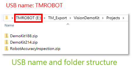
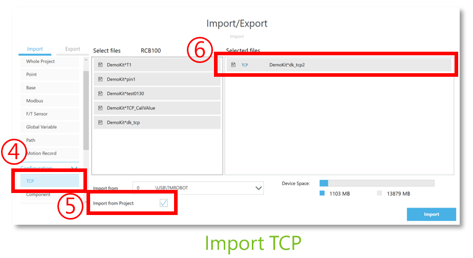
Import a Project and TCP
#
- Import:
- Project:
- Vision Demo Kit project for TMflow 1.88: DemoKit 1.88
- Vision Demo Kit project for TMflow 2.14:
- v1: DemoKit 2.14 v1
- v2: DemoKit 2.14 v2
- Vision Demo Kit project for TMflow 2.16:
- v1: DemoKit 2.16 v1
- v2: DemoKit 2.16 v2
- Checking DH calibration project: RobotAccuracyInspection Warning: Please download the corresponding project according to the Vision Demo Kit Plug-in Plate version.
Vision Demo Kit Plug-in Plate v1 Vision Demo Kit Plug-in Plate v2
- Vision Demo Kit project for TMflow 1.88: DemoKit 1.88
- TCP:dk_tcp2 (TCP import from project)
- Project:
Notice:
-
-
- TMflow Project and TCP should be imported together.
- Don’t modify the project name before importing the project.
-

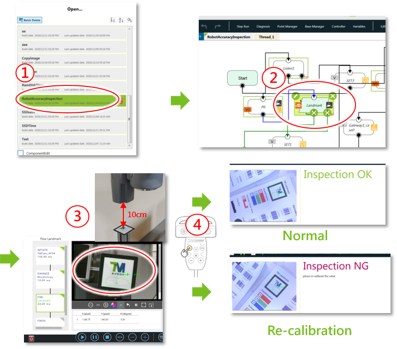
DH Calibration Check #
- Open project“RobotAccuracyInspection”
- Choose the Vision Node “Landmark”
- Move the camera above the Landmark(about 10cm) and adjust the camera parameters to ensure the Landmark is visible.
- Make sure there are no obstacles around the robot
- HM run -> Inspection OK/Inspection NG
- If the results is “Inspection NG,” perform DH calibration for the robot.
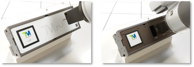
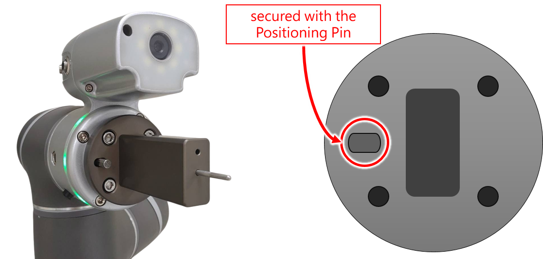
Tool Installation #
- Vision Demo Kit Tool installation is described in the figure below left.
- Vision Demo Kit Tool needs to be secured with the Positioning Pin (as shown in the figure below right).
- Remember: Remove the Positioning Pin after tightening the four screws on the flange.
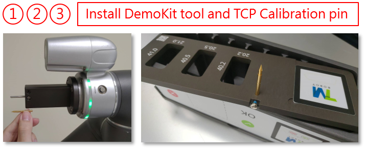
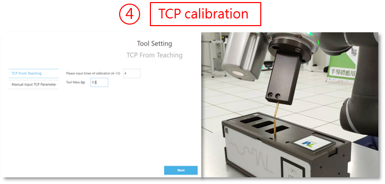
TCP Calibration #
- Perform TCP calibration after installing the Vision Demo Kit Tool.
- Replace the Vision Demo Kit Pin with a TCP Calibration Pin.
- Install another TCP Calibration Pin onto the plug-in plate.
- TCP setting
- Setting->TCP Settings->Get parameters of TCP teaching
- Count of calibration:4
- Mass: 0.2 kg
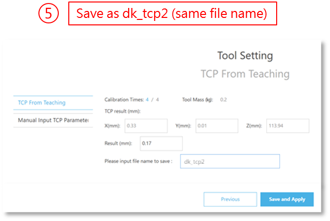
- The file name is saved as dk_tcp2, which will overwrite the old TCP value.
Initial Setup #
1. Initial Point #
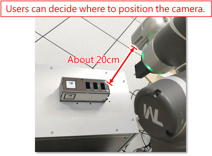
- Initial Point: Located around 20 cm above the Vision Demo Kit. The point is used to find the location of the Vision Demo Kit.
- Field of view of the initial point is the area where the Vision Demo Kit Box can be placed
- Open file: Vision_Parameter_setup(Vision Demo Kit subflow)
- Setting Method:
- Move the robot to a customized initial position.
- The initial point’s field of view constitutes the workspace (an area where the Vision Demo Kit can be placed).
- You can open the viewer to see the field of view of that point.
- Select the point P_Far_init.
- Overwrite the point with the current position.
- Move the robot to a customized initial position.
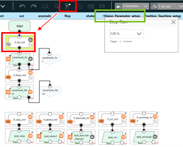
- Warning: Please do not modify the initial position of each vision node, except P_Far_init.
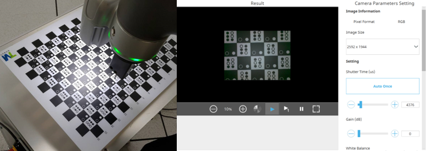
2. Adjust camera parameters #
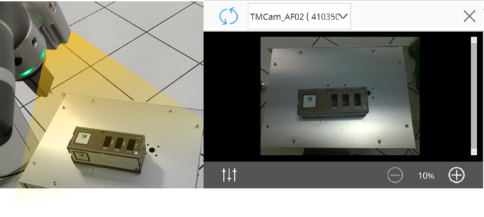
- Open file “Vision_Parameter_setup” (Vision Demo Kit subflow)
- Readjust camera parameters for all Vision Nodes.
- Move the robot to the initial position of each vision node (by using Step Run)
- The initial position is located before the vision node.
- Adjust the camera parameters:
- Place the calibration plate on the Vision Demo Kit Box
- Select “Auto Once” from top to bottom to adjust the parameters.
- If the image is overexposed, multiply the shutter time by 0.75.
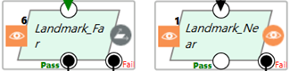
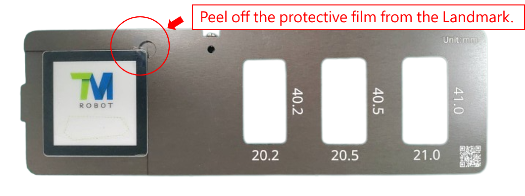
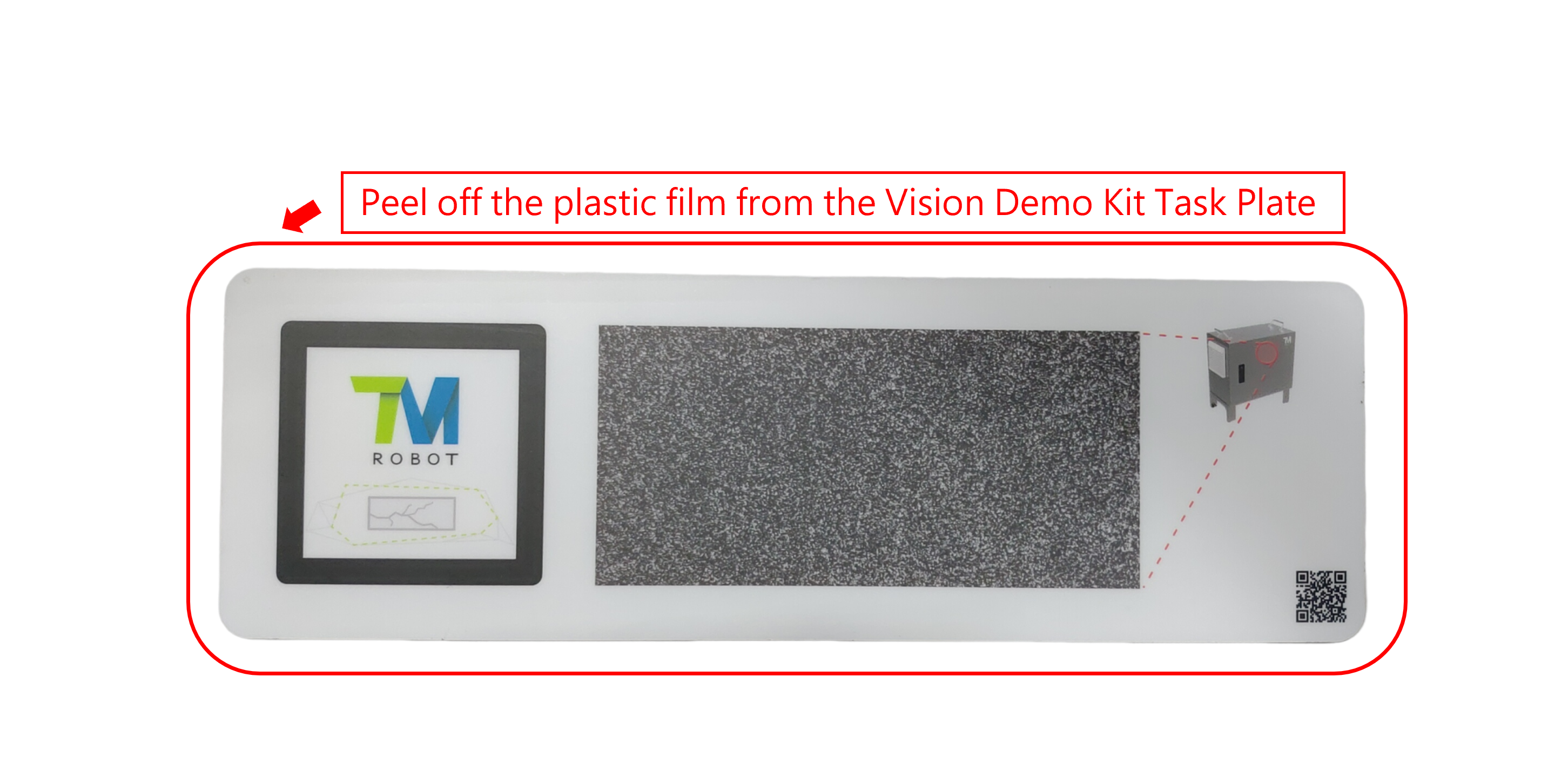
- When any of Landmark-finding tasks fail, please check if the protective film on the Landmark has been peeled off.
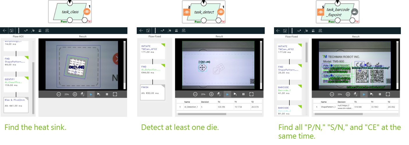
- After adjusting the camera parameters, it is necessary to save the vision project.
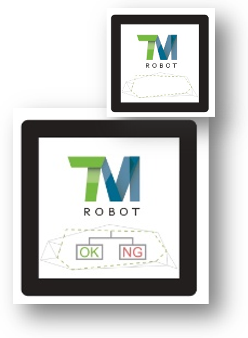
- Before saving a vision project, make sure all the following three tasks are successfully executed (see the images below).
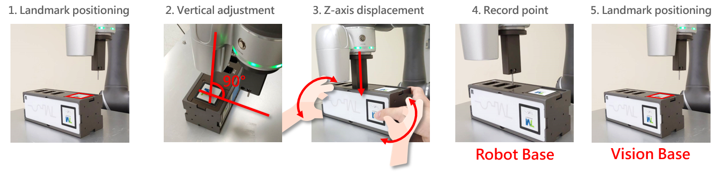
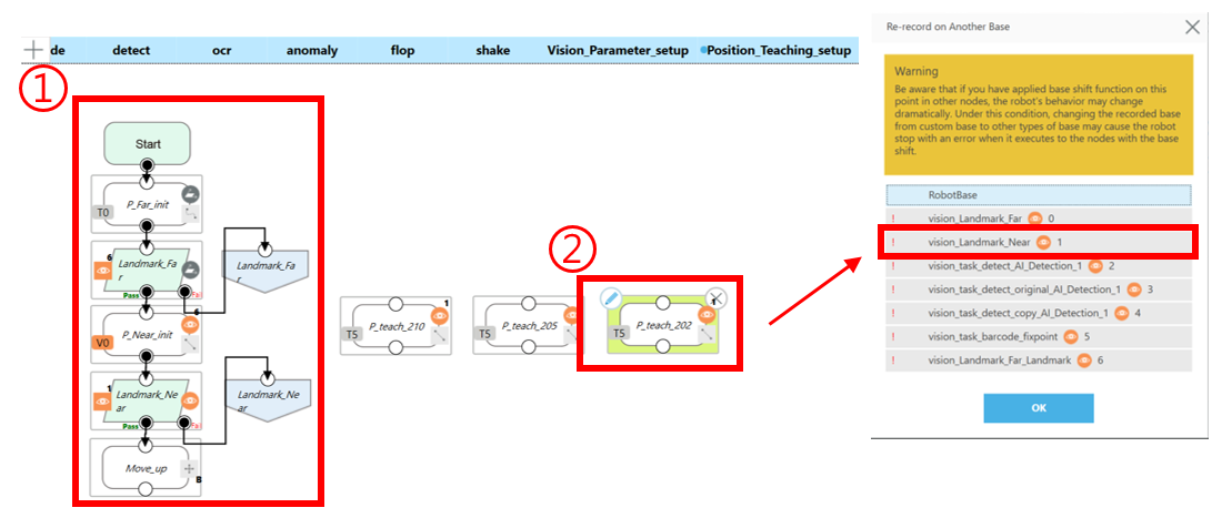
Landmark Accuracy point teaching #
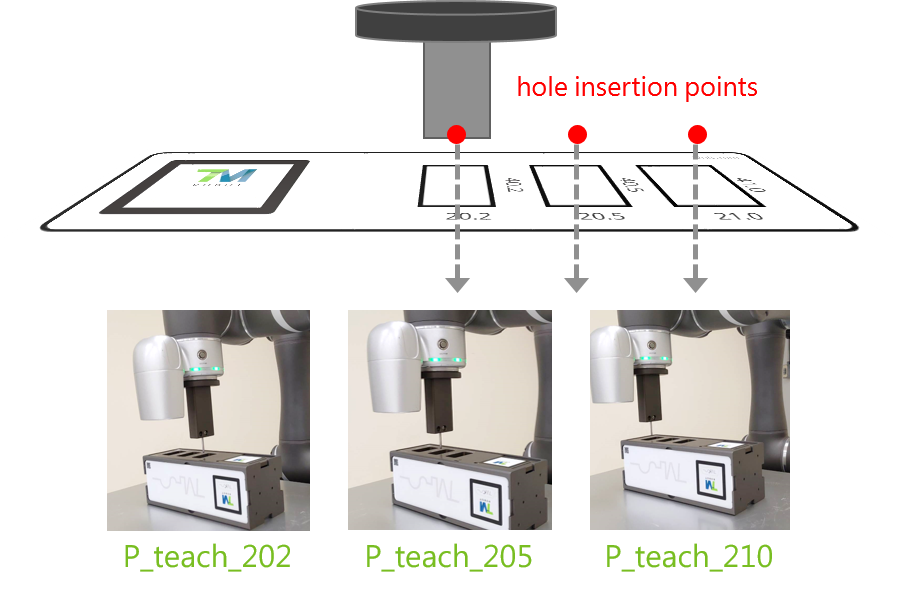
- The 3 hole insertion points in the Landmark Accuracy task need to be re-taught for different robots.
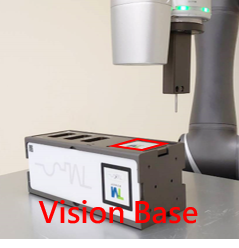
- Landmark positioning: Position the camera 10 cm above the Landmark and create a Vision Base.
- Vertical adjustment: Ensure the end effect and Vision Demo kit plate are aligned vertically
- Base: Vision Base (10 cm above the Landmark)
- Tool: dk_tcp
- Rx = 0, Ry = 0
- Z-axis displacement: Lower the end effector and manually rotate the Vision Demo Kit to align it with the hole.
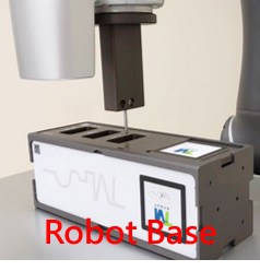
- Record point: Record a point after moving the end effector to a fixed height. (Robot Base)
- Landmark positioning: Set the point to a Vision Base
Landmark Accuracy point teaching – Tutorial Video
Landmark Accuracy point teaching – Tutorial Step
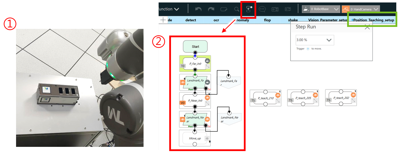
1. Landmark positioning #
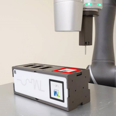
- DemoKit: Place the Landmark Accuracy plate in the initial position P_Far_init’s field of view.
- Please place the Vision Demo Kit box on a flat surface.
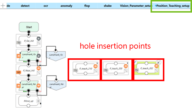
- Open file “Position_Teaching_setup” (Vision Demo Kit subflow)
- Step-run the processes sequentially

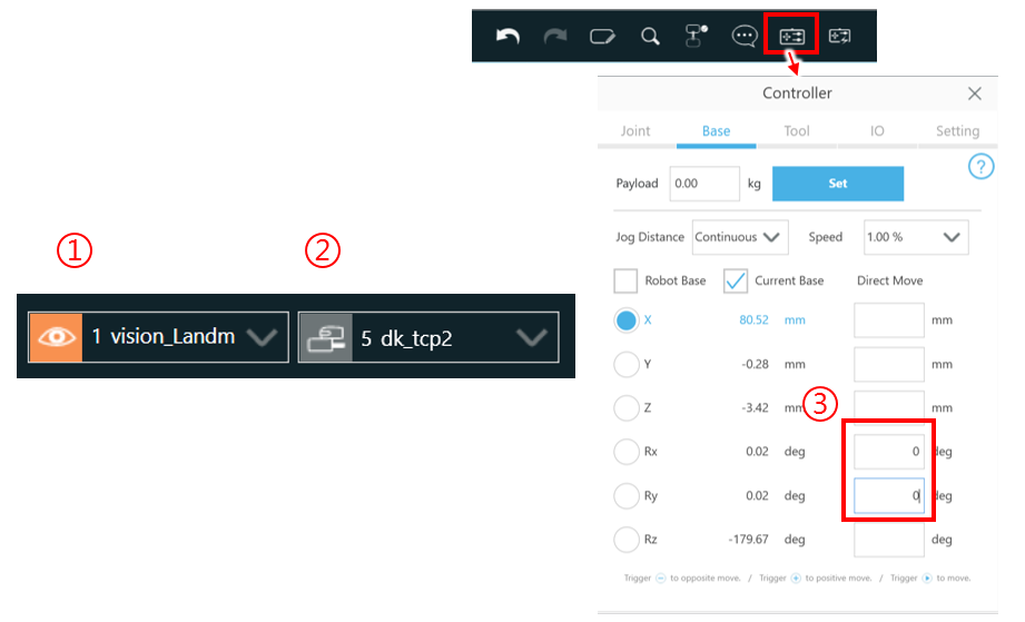
2. Vertical adjustment #
- Set base to vision_Landmark_near
- Set the tool to dk_tcp2
- Set Controller as follows:
- Rx = 0
- Ry = 0
3. Z-axis displacement #
- Set Controller:
- Move above the target hole (roughly).
- Set Controller:
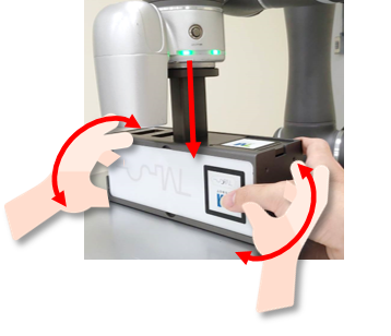
- End effector moves down
- Manually re-position the Vision Demo Kit Box so the tool can penetrate the holes on the box
- Make sure the tool can pass through the holes.
- Try to align the tool with the center of the holes
- Tip: To prevent the tool from colliding with the box, keep moving the tool up and down using the controller.
——Do not move the Vision Demo Kit until the teach process is finished.—–
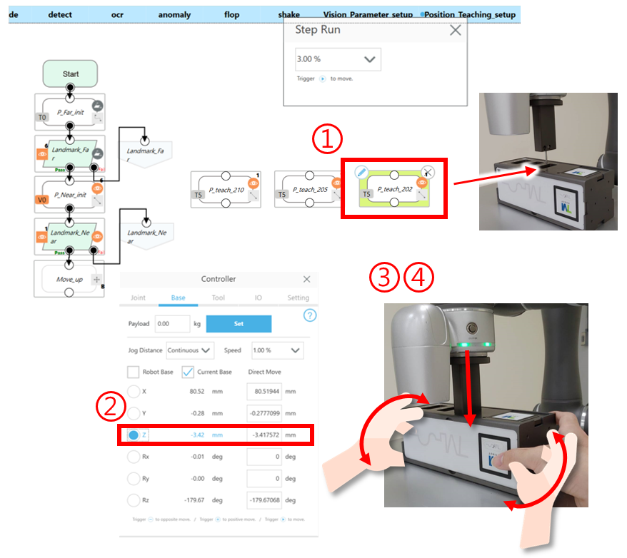
4. Record point #
- Set Controller
- Adjust it to a fixed height. (z= -3.5)
- Rx = 0, Ry = 0, leave the other fields empty.
- Overwrite the teaching point.
- Set the point to the Robot Base.

5. Landmark positioning #
- Step-run the processes sequentially
- Set the point back to the Vision Base vision_Landmark_Near.
—– Complete teaching of positions——
- Repeat the steps above until the other two points have been taught.
- There are three points that need to be taught; they each are on their own and don’t interact with each other.
Appendix #
Extra accessories #
- There are three tasks require the use of additional accessories for demo
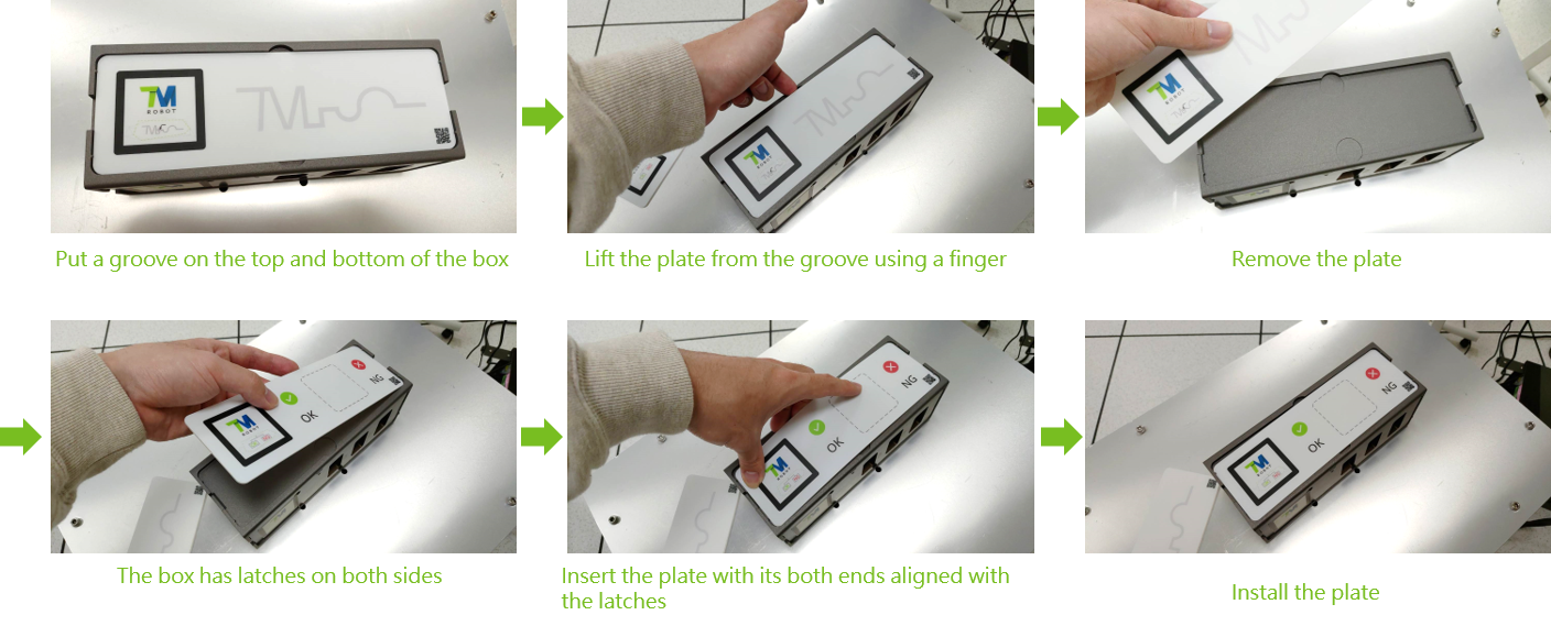
Replace a plate
#
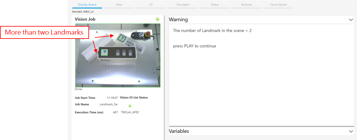
Detect multiple Landmarks
#
- When there are two or more landmarks in the workspace, pause the project to avoid causing unexpected actions.
- Warning: TMflow Version 1.88 cannot detect multiple landmarks. To prevent any unexpected behaviors, please make sure the camera finds only ONE landmark in its FOV.


