- Download the Calibration TMflow Project
- New Calibration Solution - Calibration Using TMflow Project
- Supported Calibration Functions
- Standard/Customized Calibration Mode
- How to Run the Calibration Project
- Downloading Project
- Importing Project
- Overview of the Calibration Project
- Basic Settings Process
- Run Project
- Calibration Results
Examples are valid for:
TMflow Software version: 2.16 or above.
TM Robot Hardware version: All versions.
Other specific requirements: None
Note that older or newer software versions may have different results.
Download the Calibration TMflow Project #
- To download, go visit (Download Center) on Techman Robot Official Website.
- File Location : Download Center > Support Software > Other > Calibration_Project_TM_[TMflow Version].zip
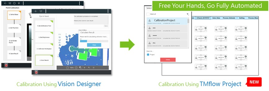
New Calibration Solution – Calibration Using TMflow Project #
- Perform vision calibration via TMflow project.
- Advantages :
- Customizable Speed : Users can adjust the project execution speed, reducing calibration time to under 5 minutes.
- Customizable Points: Users can customize calibration points, no longer restricted by the installation form and size of external cameras and the end effector.
- Collision Check: The points come with Collision Check, preventing collisions during the calibration process.
- No Repetitive Configuration: After completing the initial setup, the project can be reused.
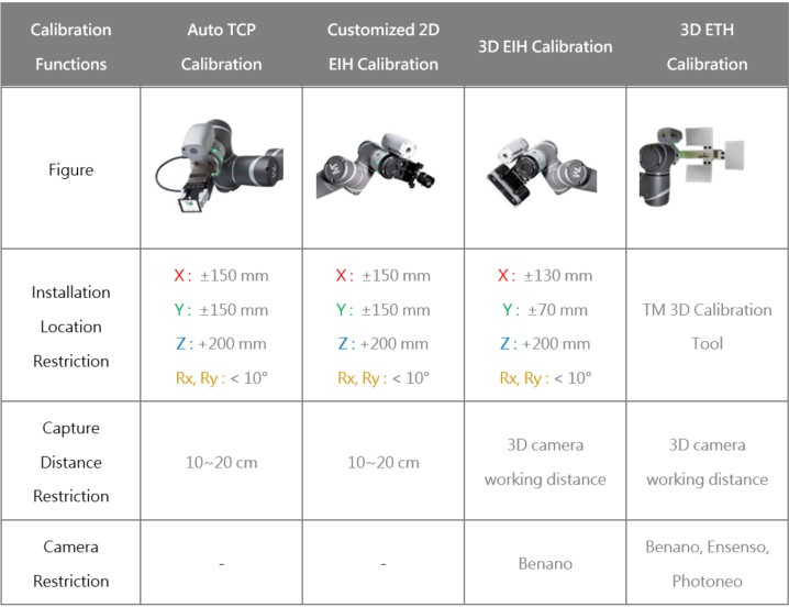
 Supported Calibration Functions #
Currently supports calibration functions using the TMflow project.
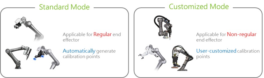
Standard/Customized Calibration Mode #
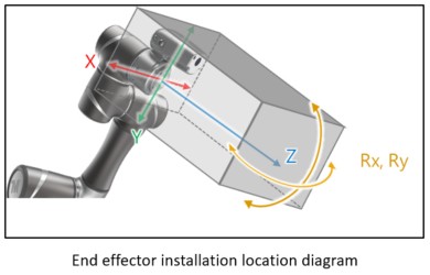
- End effectors are categorized as regular or non-regular based on their installation location and size.
- Regular end effector can run the standard calibration mode, while non-regular end effector is recommended to run the customized mode.
- In the standard mode, calibration points are generated automatically, while in the customized mode, users need to define their own calibration points.
Regular end Effector Definition #
In Customized Mode, 3D EIH/ETH Calibration applies to all 3D cameras.
How to Run the Calibration Project #
Operating Procedures
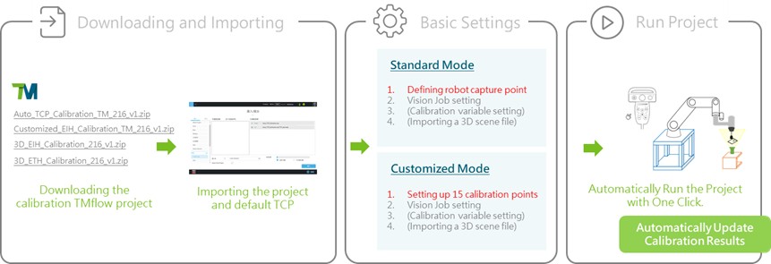
Downloading Project #
Download the calibration TMflow Project.
- To download, go visit (Download Center) on Techman Robot Official Website.
- File Location : Download Center > Support Software > Other > Calibration_Project_TM_[TMflow Version].zip
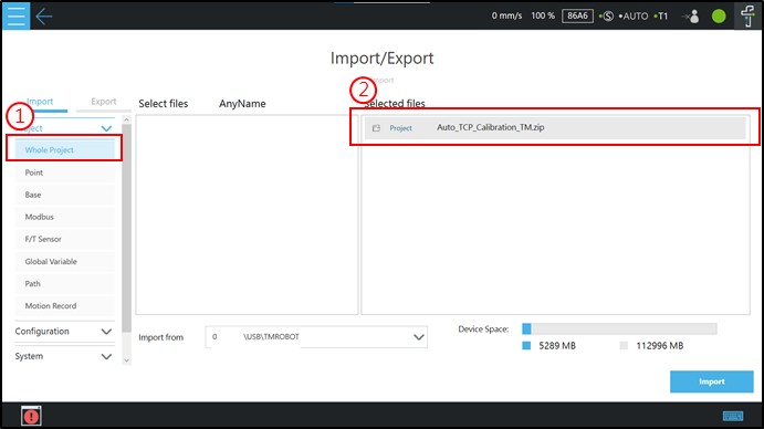
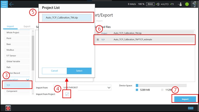
Importing Project #
To run the project, import it and the default TCP into your robot.
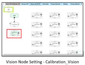
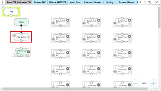
Overview of the Calibration Project #
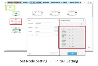
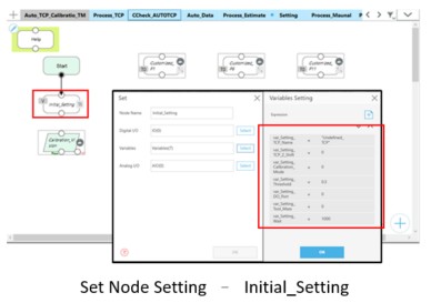
To make it easy to set up the project, all the nodes that need to be set up are included in the Subflow Setting. Nodes that do not need to be configured are made inaccessible by a project lock, lest the are wrongly edited by the user.
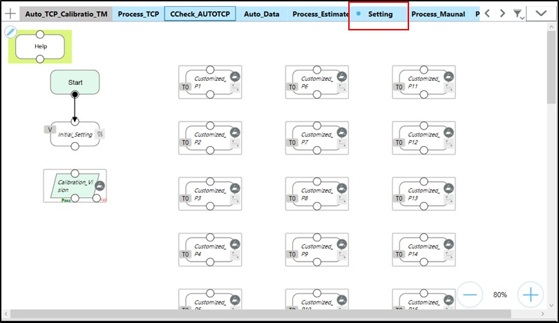
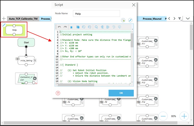
You can consult the Help Node for straightforward instruction on node setup.
Basic Settings Process #
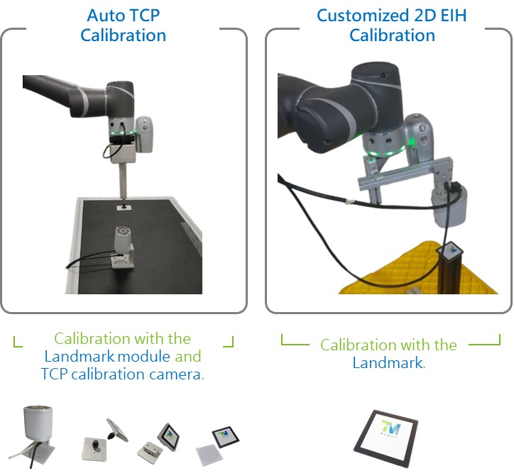
Auto TCP #
NOTE : Confirm the robot has completed hand-eye and DH calibration first.
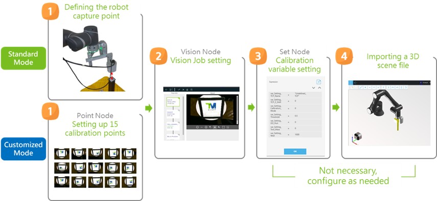
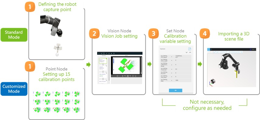
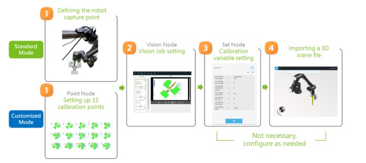
- The execution of the calibration project requires four basic settings as shown in the figure.
- The only difference in the basic settings between standard mode and customized mode occurs in Step One.
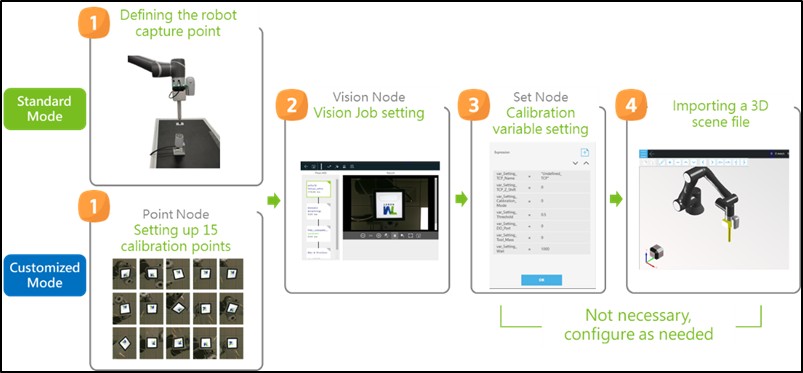
1. Defining the Robot Capture Point (Standard Mode) #
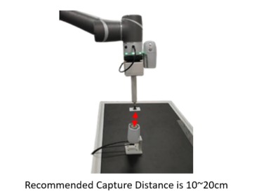
- Under the standard calibration mode, the robot system generates calibration points on its own, so all you need to do is manipulate the robot to its initial capture point.
- The project loads the robot’s current position and users that position as its capture point; this point does not need to be overwritten or generated.
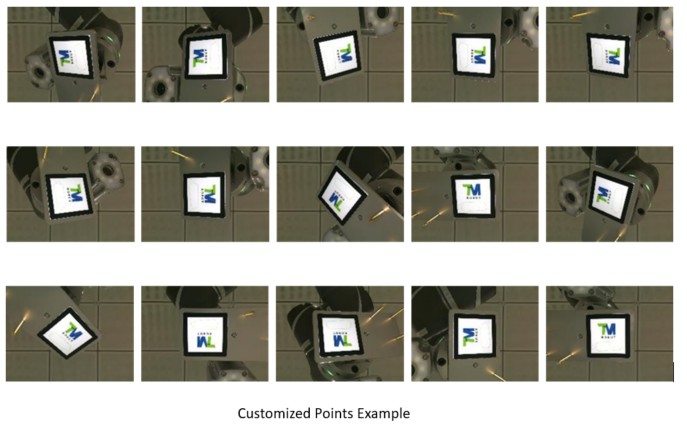
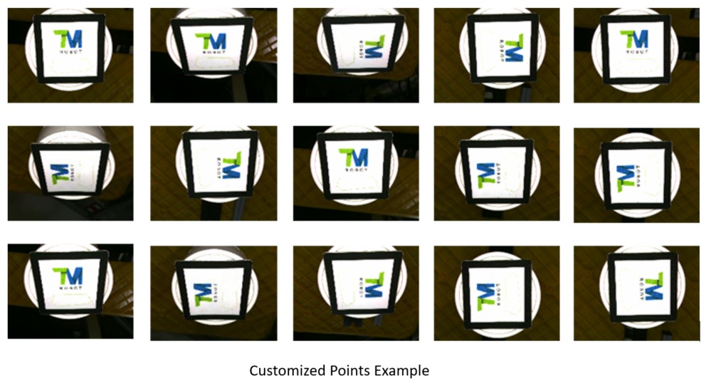
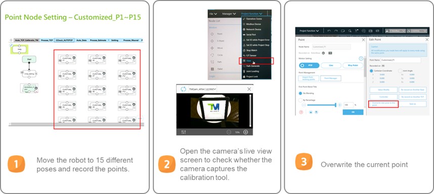
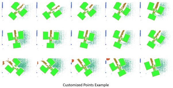
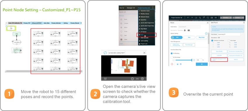
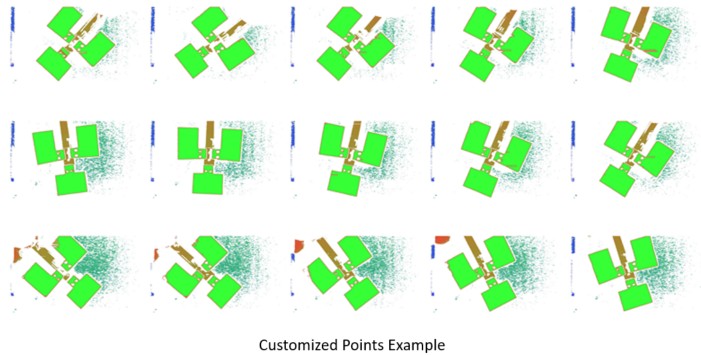
1. Setting up 15 Calibration Points (Customized Mode) #
Users need to create a set of 15 calibration points under the customized node.
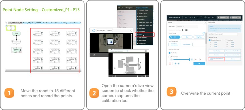
Adjusting Points Tip:
- Rotating J6, which is the z-axis of the tool base.
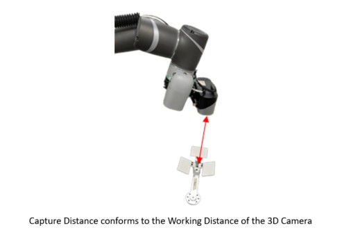
- Make sure all poses are different.
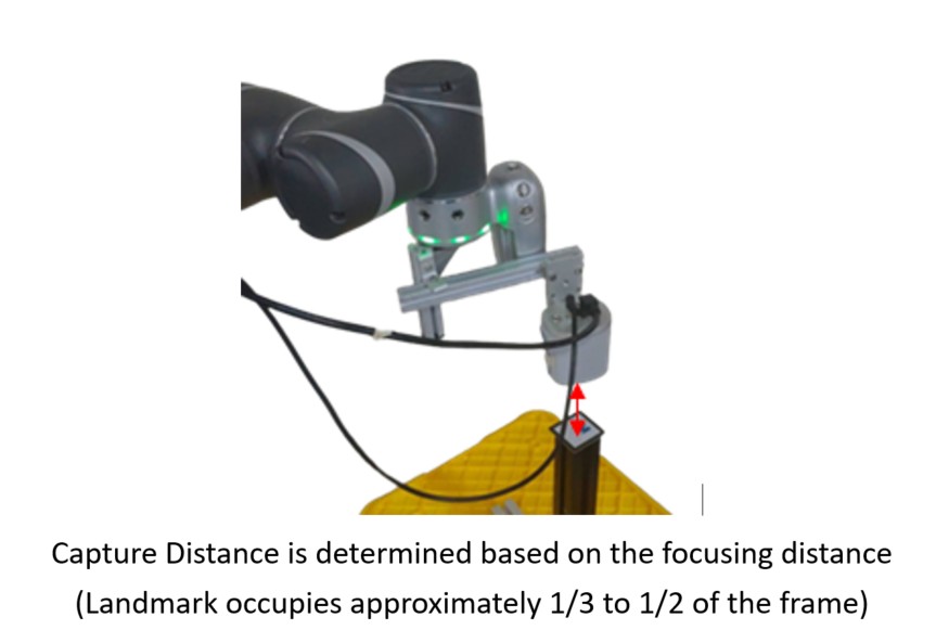
- Photographing the calibration tool in its entirety.
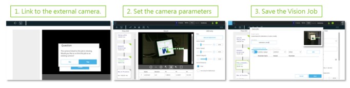
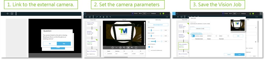
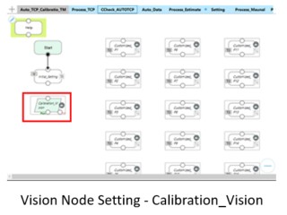
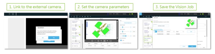
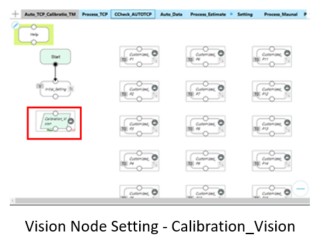
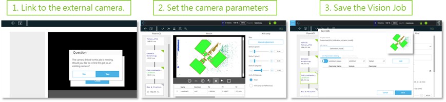
 2. Vision Job Setting #
- Set up the camera’s parameters to make sure it can detect the calibration tool.
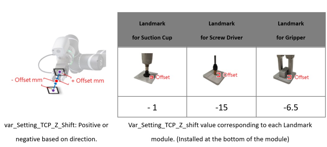
- Calibration tool :
- Auto TCP Calibration : Landmark module
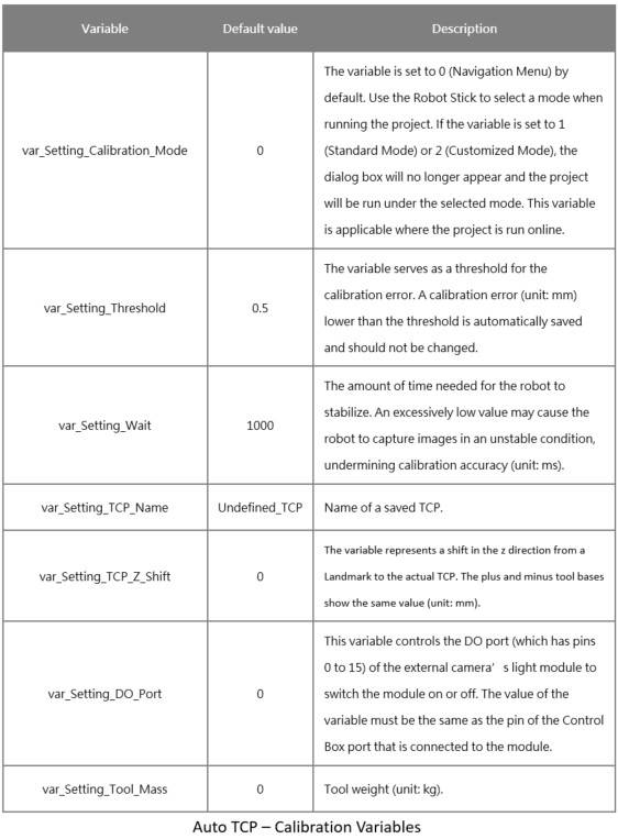
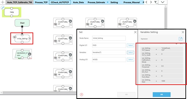
 3. Calibration Variable Setting #
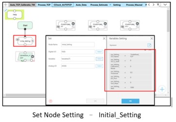
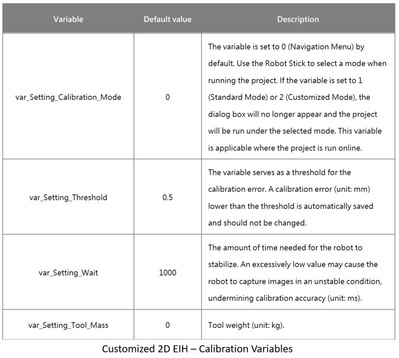
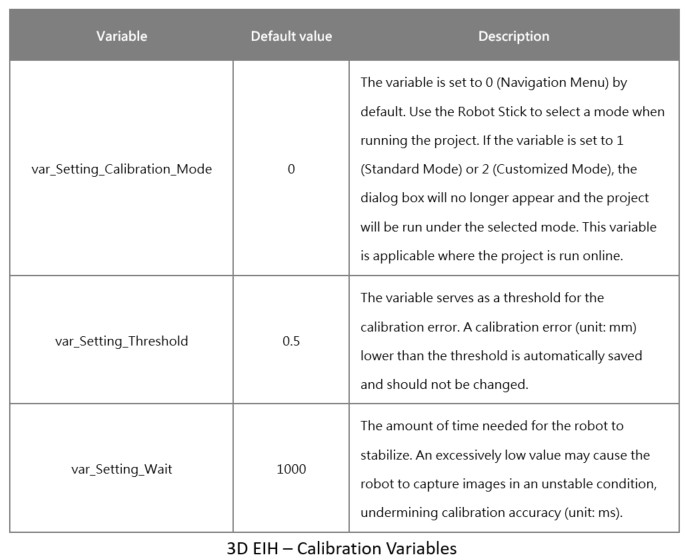
The project offers customizable calibration variables, which have their own default values and can be edited. These calibration variables are described in the following table.
4. Importing a 3D Scene File #
All calibration points have Collision Check, but to maximize the use of this feature you need to import the 3D CAD files of a tool and scene. A 3D CAD file must meet the following requirements:
- The file extension of a 3D CAD file must be .step.
- The 3D CAD file of a tool must be named TCP_estimate.
NOTE: For instructions on how to use the 3D CAD files of a tool and 3D scene, see Chapter Collision Check in Software Manual TMflow, where you will learn to create the CAD files of a tool and scene using TMstudio and import the files into TMflow.
- To download TMflow manual, go visit Download Center on Techman Robot official website.
- Manual file location : Download Center > Manual > TMflow
Customized 2D EIH #
Note : Confirm the robot has completed hand-eye and DH calibration first.
- The execution of the calibration project requires four basic settings as shown in the figure.
- The only difference in the basic settings between standard mode and customized mode occurs in Step One.
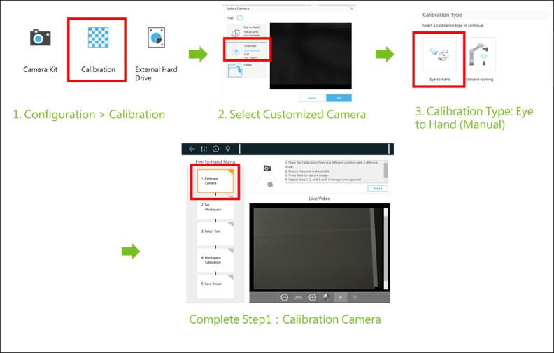
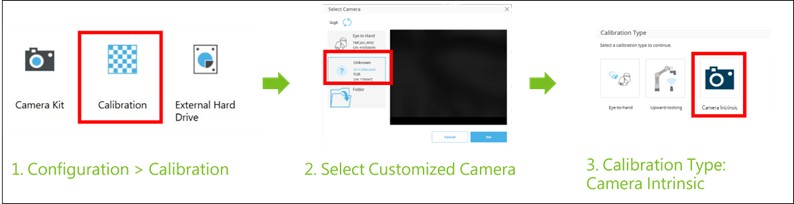
 Before performing customized EIH calibration, it is necessary to complete the camera intrinsic calibration of the customized EIH camera.
The adjustment methods for external camera aperture, focal length, etc., can be referenced in the technical document at [Notice on External Camera Calibration]
1. Defining the robot capture point (Standard Mode) #
- Under the standard calibration mode, the robot system generates calibration points on its own, so all you need to do is manipulate the robot to its initial capture point.
- The project loads the robot’s current position and users that position as its capture point; this point doesn’t need to be overwritten or generated.
1. Setting up 15 calibration points (Customized Mode) #
Users need to create a set of 15 calibration points under the customized mode.

Adjusting Points Tip :
- Rotating J6, which is the z-axis of the tool base.
- Making sure all poses are different.
- Photographing the calibration tool its entirety.
2. Vision Job Setting #
- Set up camera’s parameters to make sure it can detect the calibration tool.
- Calibration tool :
- Customized EIH Calibration : Landmark
3. Calibration variable Setting #
The project offers customizable calibration variables, which have their own default values and can be edited. These calibration variables are described in the following table.
4. Importing a 3D scene file #
All calibration points have Collision Check, but to maximize the use of this feature you need to import the 3D CAD files of a tool and scene. A 3D CAD file must meet the following requirements:
- The file extension of a 3D CAD file must be .step.
- The 3D CAD file of a tool must be named TCP_estimate.
NOTE: For instructions on how to use the 3D CAD files of a tool and 3D scene, see Chapter Collision Check in Software Manual TMflow, where you will learn to create the CAD files of a tool and scene using TMstudio and import the files into TMflow.
- To download TMflow manual, go visit (Download Center) on Techman Robot official website.
- Manual file location : Download Center > Manual > TMflow
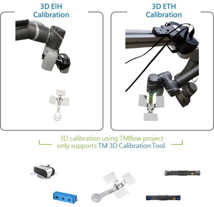
3D EIH #
NOTE : Confirm the robot has completed hand-eye and DH calibration first.
- The execution of the calibration project requires four basic settings as shown in the figure.
- The only difference in the basic settings between standard mode and customized mode occurs in Step One.
1. Defining the robot capture point (Standard Mode) #
- Under the standard calibration mode, the robot system generates calibration points on its own, so all you need to do is manipulate the robot to its initial capture point.
- The project loads the robot’s current position and users that position as its capture point; this point dosen’t need to be overwritten or generated.
1. Setting up 15 calibration points (Customized Mode) #
Users need to create a set of 15 calibration points under the customized mode.
Adjusting Points Tip :
- Rotating J6, which is the z-axis of the tool base.
- Making sure all poses are different.
- Photographing the calibration tool in its entirety.
2. Vision Job Setting #
- Set up the camera’s parameters to make sure it can detect the calibration tool.
- Calibration tool :
- 3D EIH Calibration : TM 3D Calibration Tool
3. Calibration variable setting #
The project offers customizable calibration variables. which have their own default values and can be edited. These calibration variables are described in the following table.
4. Importing a 3D scene file #
All calibration points have Collision Check, but to maximize the use of this feature you need to import the 3D CAD files of a tool and scene. A 3D CAD file must meet the following requirements :
- The file extension of a 3D CAD file must be .step.
- The 3D CAD file of a tool must be named TCP_estimate.
NOTE : For instructions on how to use the 3D CAD files of a tool and 3D scene, see Chapter Collision Check in Software Manual TMflow, where you will learn to create the CAD files of a tool and scene using TMstudio and import the files into TMflow.
- To download TMflow manual, go visit Download Center on Techman Robot official website.
- Manual file location : Download center > Manual > TMflow
3D ETH #
NOTE : Confirm the robot has completed hand-eye and DH calibration first.
- The execution of the calibration project requires four basic settings as shown in the figure.
- The only difference in the basic settings between standard mode and customized mode occurs in Step One.
1. Defining the robot capture point (Standard Mode) #
- Under the standard calibration mode, the robot system generates calibration points on its own, so all you need to do is manipulate the robot to its initial capture point.
- The project loads the robot’s current position and users that posiiton as its capture point; this point doesn’t need to be overwritten or generated.
1. Setting up 15 calibration points (Customized Mode) #
Users need to create a set of 15 calibration points under the customized mode.
Adjusting Points Tip :
- Rotating J6, which is the z-axis of the tool base.
- Making sure all poses are different.
- Photographing the calibration tool in its entirety.
2. Vision Job Setting #
- Set up the camera’s parameters to make sure it can detect the calibration tool.
- Calibration tool :
- 3D ETH Calibration : TM 3D Calibration Tool
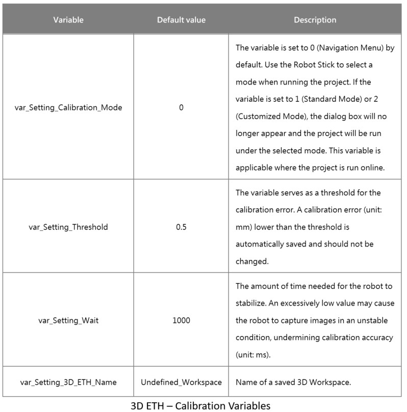
3. Calibration variable setting #
The project offers customizable calibration variables, which have their own default values and can be edited. These calibration variables are described in the following table.
4. Importing a 3D scene file #
All calibration points have Collision Check, but to maximize the use of this feature you need to import the 3D CAD files of a tool and scene. A 3D CAD file must meet the following requirements:
- The file extension of a 3D CAD file must be .step.
- The 3D CAD file of a tool must be named TCP_estimate.
NOTE: For instructions on how to use the 3D CAD files of a tool and 3D scene, see Chapter Collision Check in Software Manual TMflow, where you will learn to create the CAD files of a tool and scene using TMstudio and import the files into TMflow.
- To download TMflow manual, go visit Download Center on Techman Robot official website.
- Manual file location: Download Center > Manual > TMflow
Run Project #
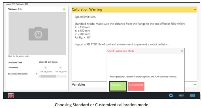
Choosing Standard or Customized calibration mode #
- After the project is set up, press the Play button on the Robot Stick to run the project.
- Once the project begins, the system asks you to choose between Standard and Customized. Press the + and – buttons on the Robot Stick to shift between the modes and the Play button to select either.
NOTE: Since calibration is performed through a project, you can change the project’s speed, which should not exceed 50%. If you are going to run a calibration project for the first time, use a 15% speed. Then hold the Robot Stick until the project is finished, so that you can immediately stop the project in case of a collision.
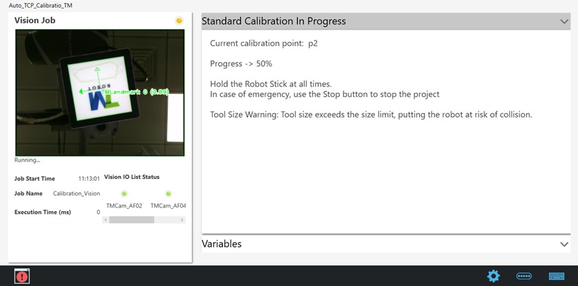
Standard Calibration Mode #
Once the project is run under the standard calibration mode, rough TCP values are obtained by moving the robot slightly and the robot is moved to the calibration points automatically generated. The Display Board tells you calibration status and progress; once the progress reaches 100%, calibration is finished.
Once the customized calibration project is finished, the result could be succeeded, failed, or warning.
- Succeeded
- Calibration succeeded: Calibration succeeded, with a smaller error than recommended. The result is saved automatically.

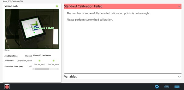
- Failed
- Calibration failed: Fewer than enough calibration points are successfully detected.
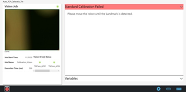
-
- Wrong initial position : The camera cannot detect the Landmark at the initial position.
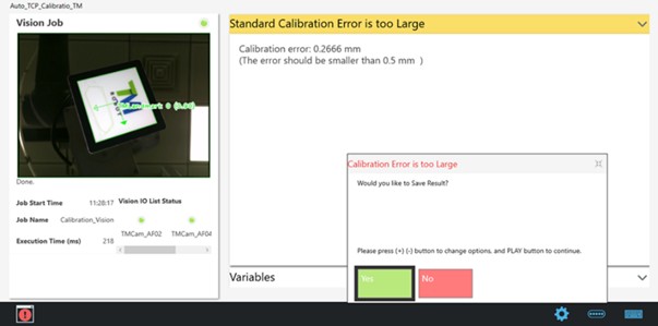
- Warning
- Calibration error is too large: Calibration is finished but the error is larger than recommended. The system asks the user whether to save the calibration result.
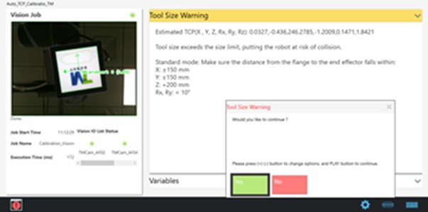
-
- The tool does not suit the standard calibration mode: The tool size is not compatible with the standard calibration mode. The system asks the user whether to continue.
Customized Calibration Mode #
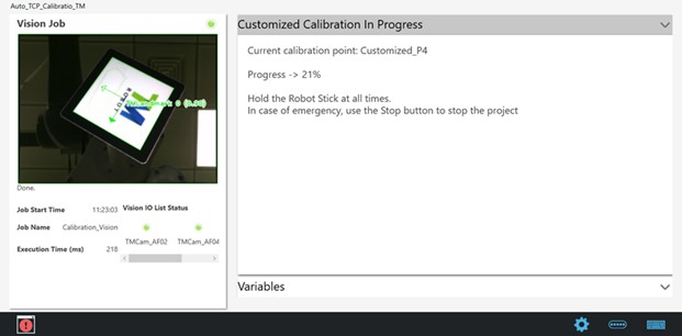
When customized calibration starts, the robot moves to custom calibration points sequentially, from Customized_P1 to Customized_P15. The Display Board tells you calibration status and progress; once the progress reaches 100%, calibration is finished.
Once the customized calibration project is finished, the result could be succeeded, failed, or warning.
- Succeeded
- Calibration succeeded : Calibration succeeded, with a smaller error than recommended. The result is saved automatically.

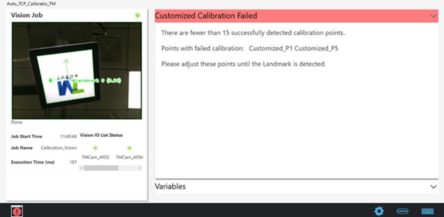
- Failed
- Calibration failed: The camera cannot detected the Landmark at some of the custom calibration points. Calibration points with failed calibration are shown on the screen.
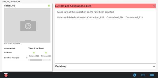
-
- Calibration points not set up: Not all calibration points have been set up. Points that are not set up are shown on the screen.
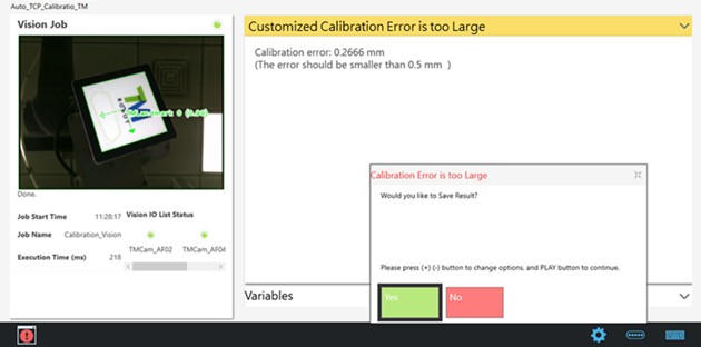
- Warning
- Excessively large calibration error: Calibration is finished but the error is larger than recommended. The system asks the user whether to save the calibration result.
Calibration Results #
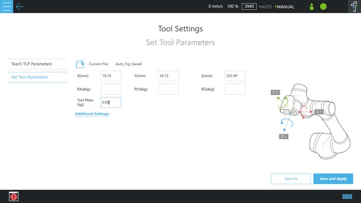
Auto TCP #
- After calibration is finished, the TCP calibration result is automatically saved. To check the TCP calibration result, go to Configuration > Tool Settings.
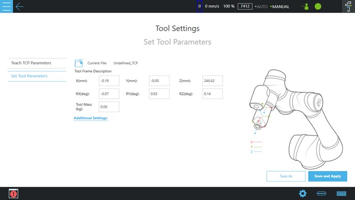
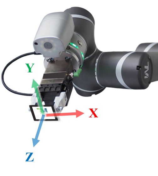
- After auto-TCP calibration, you will obtain the axial directions of the tool, which determine where the Landmark should face.
Customized 2D EIH #
- After calibration is finished, the customized EIH calibration result is automatically saved (The name is fixed as HandCamera2). To check the customized EIH calibration result, go to Configuration > Tool Settings.
- A robot can only accommodate one external 2D camera.
- Customized EIH camera supported functions:
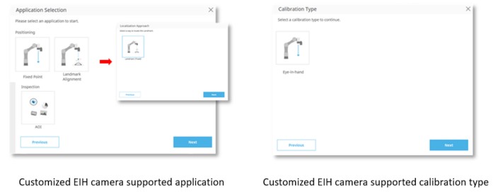
NOTE: Customized EIH camera not support IO trigger functions.
3D EIH #
- The system will automatically update the calibration result for 3D EIH camera, and users do not need to make any settings.
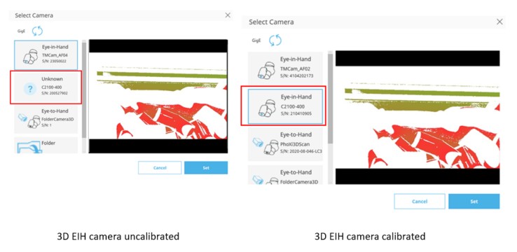
- A robot can only accomodate one external 3D camera
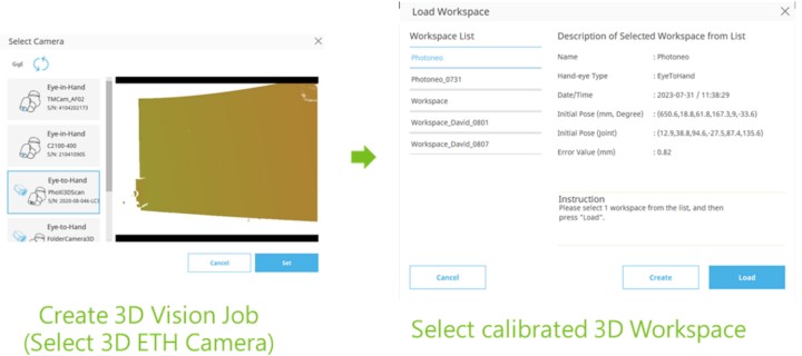
3D ETH #
- After calibration is finished, 3D ETH calibration result is automatically saved. To check the 3D ETH calibration result, go to Create 3D Vision Job > Load Workspace.