TMflow Software version: 2 Series
TM Robot Hardware version: All Robot with EIH Camera
Jig: A fixture designed to be mounted on the FOUP with a tolerance of ±0.05 mm, and capable of supporting LM attachment.
Background #
In Robot + AMR integrated applications, system integrators typically use the Landmarks (LM) attached to each slot on the E-Rack to establish the LM Base. This LM Base is then used as the reference for teaching the FOUP pick-and-place points.
Ideally, once the teaching is completed, the same LM Base should be applicable to all slots. However, in actual operation, the following factors often introduce variations:
A. Nonlinear errors may occur when the robot performs Cartesian movements in different postures.
B. Inconsistencies in LM attachment positions or orientations across slots can also lead to pick-and-place deviations.
These errors may cause the robot’s actual physical position to deviate when moving to the intended pick-and-place points, potentially resulting in mechanical interference.
At present, most system integrators still rely on manually fine-tuning the offsets for each slot individually. This process is time-consuming, labor-intensive, and in urgent need of a more efficient solution.
Introduction & Value #
This method effectively resolves issue B, namely the pick-and-place errors caused by inconsistencies in the LM attachment positions across slots. With this approach, when the robot performs pick-and-place operations at each slot under similar postures, no additional manual fine-tuning is required. The pick-and-place accuracy can be maintained within ±1 mm, significantly reducing the amount of manual work required.
For example:
Suppose there are 100 slots on site. With the traditional approach, each slot requires individual teaching and fine-tuning, taking approximately 10 minutes per slot—resulting in a total of 100 × 10 = 1,000 minutes.
With the new method, the workflow becomes:
• Initial pick-and-place teaching: approximately 10 minutes
• For all remaining slots, only 1 minute per slot is needed to run the vision task and establish the required relationship
In total, only 10 + (1 × 100) = 110 minutes are needed to complete the pick-and-place point setup for all slots—saving nearly 90% of the time compared to the traditional process while also reducing the likelihood of human error.
Preparation #
TMflow Software version: 2 Series
TM Robot Hardware version: All Robot with EIH Camera
Jig: A fixture designed to be mounted on the FOUP with a tolerance of ±0.05 mm, and capable of supporting LM attachment.

Optimization Method & Process #
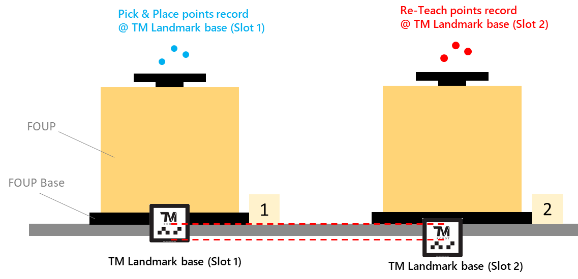
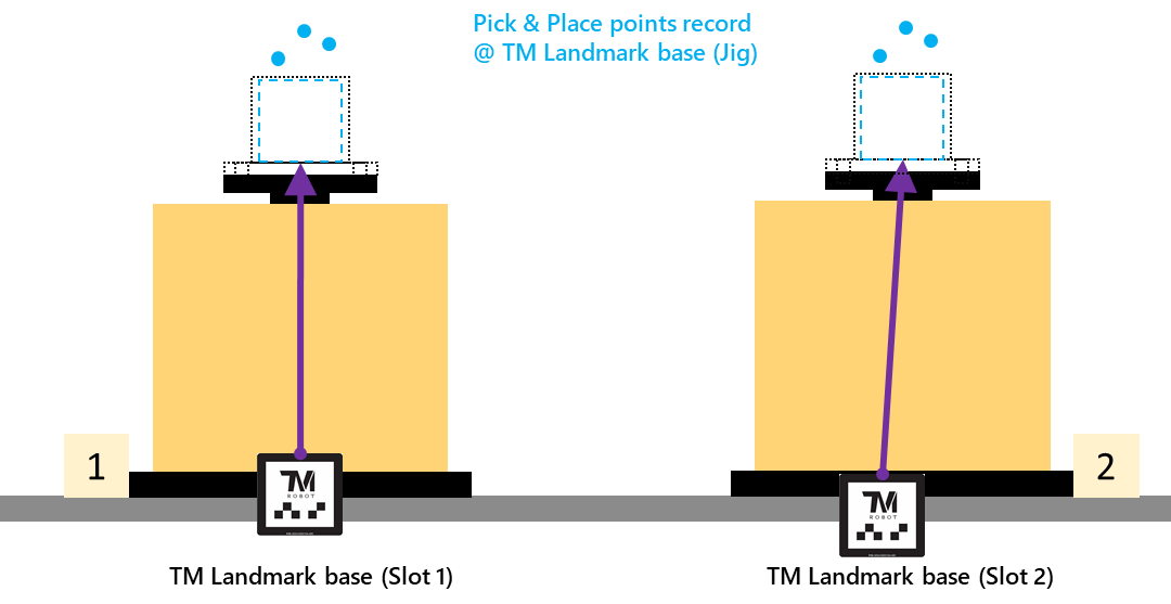
- First, record the pick-and-place points by manually teaching based on the TM LM Base (Jig). These points can then be carried along with the Jig to the next slot, eliminating the need for re-teaching.
- Next, establish the relationship between each TM LM Base (slot) and the TM LM Base (Jig).
- During actual operation, the Jig is no longer required. After the robot executes the TM LM Base (Slot) vision job, the pick-and-place coordinate frame is computed through the TM LM Base (Slot) along with the transformation relationship. Therefore, the LM on the Jig is not needed in runtime.
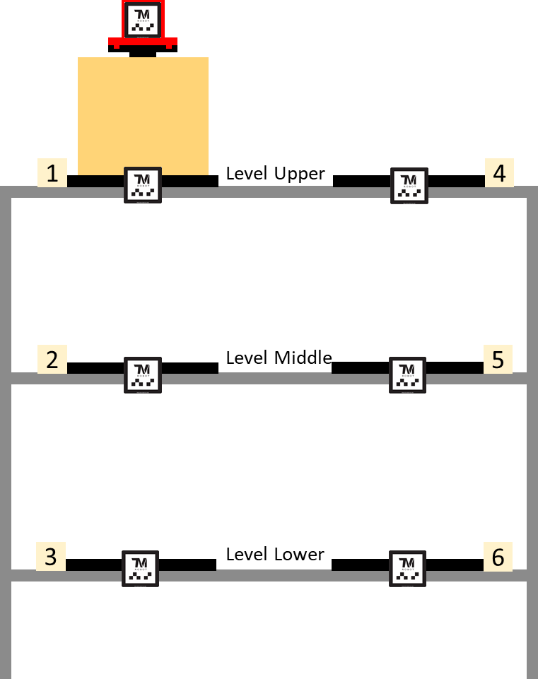
The following example uses a multi-layer E-Rack (Slot 1 to Slot 6) to illustrate how this method is used to establish the correspondence between Landmarks and complete the pick-and-place operations for each slot.
System Architecture #
As shown in the illustration above, a Rackwith upper, middle, and lower layers includes:
- 6 FOUP Base
- 6 TM Landmark
- FOUP(Front Opening Unified Pod)
- Jig(With Landmark)
The robot defines the relative relationships between each Slot Landmark and the Jig Landmark, allowing all pick-and-place operations to be performed based on a unified reference frame.
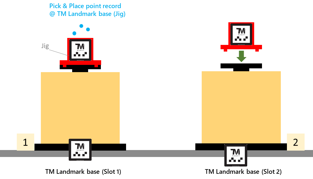
Teaching Procedure #
- Start from any level, for example, begin with Level Upper (Slot 1).
- Mount the Cap Jig on top of the FOUP.
- Step-run the project (the long-distance LM capture point must be preconfigured).
- LM fixed-point localization (Slot Landmark) :
- The robot first performs long-distance and close-up captures to obtain the Slot LM and generate the corresponding VisionBase_Slot.
- LM fixed-point localization (Slot Landmark) :
-
- LM fixed-point localization (Jig Landmark):
- Then, it performs long-distance and close-up captures for the Jig LM to obtain VisionBase_Jig.
- LM fixed-point localization (Jig Landmark):
- Teach the pick-and-place points.
- Teach the pick-and-place points based on VisionBase_Jig.
- Repeat the same steps to complete the teaching of pick-and-place points for the remaining levels (Level Middle / Level Lower) in sequence.
Global Variables #
If the system contains N slots, then N sets of global variables must be created in TMflow.
For example:
For example:

Project Execution Flow #
- Define Stage
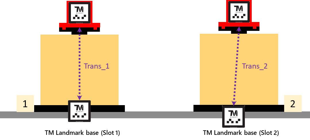
- Establish the relative relationship (Transformation Matrix) between VisionBase_Slot and VisionBase_Jig.
- Store the result into the corresponding global variable.
For Example :
-
- Relationship for Slot 1 → g_Z_Slot_Trans_1
- Relationship for Slot 2 → g_Z_Slot_Trans_2
- …
- Relationship for Slot N → g_Z_Slot_Trans_N
- Start from any slot (e.g., Slot 1). After completing the relationship definition, proceed to the next slot.
- Complete the Transformation Matrix setup for all remaining slots (Slot 2 to Slot 6).
2. Run Stage
- When the MES or upper-level system issues a work order, the system can update the variable ID according to the assigned slot.
- The robot project automatically applies the corresponding slot’s transformation relationship and completes the pick-and-place operation.
Q&A #
Q. How is the relationship between the Slot LM and Jig LM established in the project, and how is it used?
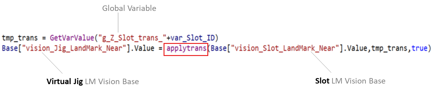
A. During the Define stage of the project, a Script Node combined with the TMscript command Trans() is used to compute the transformation between the two LM Bases. The resulting relationship is then stored in the corresponding global variable.

In addition, during the Run stage of the project, the TMscript command ApplyTrans() is used to generate the virtual Jig LM coordinate frame.
Q. How can the positioning accuracy of the LM Base be improved?
A. In addition to ensuring adequate lighting, it is recommended to add a waiting time before capturing images in the Vision Job (e.g., using a Waitfor node with 1000 ms). This ensures that the robot remains stable and motionless during image capture, improving detection consistency.
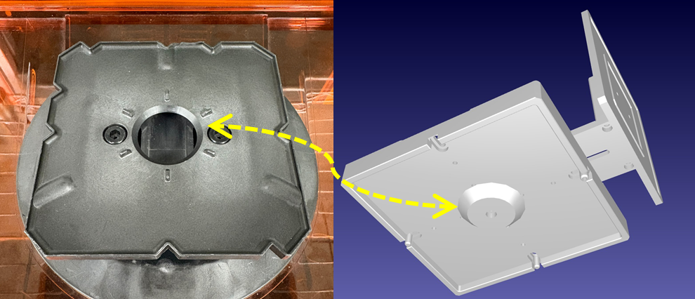
Q. Are there any suggestions for designing the Jig?
A. The primary purpose of the Jig is to maintain a fixed relationship between the upper LM and the FOUP. Therefore, the recommended design approach is to minimize LM misalignment by ensuring a precise and stable fit. For example, the bottom of the Jig may include a tapered alignment feature to center it on the FOUP, ensuring consistent positioning during each installation.
If designing a Jig is considered too complicated, an alternative approach is to directly attach an LM onto a FOUP and use it as a golden sample. This also fulfills the purpose of maintaining a fixed relationship between the upper LM and the FOUP. However, compared with manufacturing a Jig, a FOUP is generally more expensive. Therefore, the choice between these two approachs should be made based on the actual conditions and cost considerations on site.
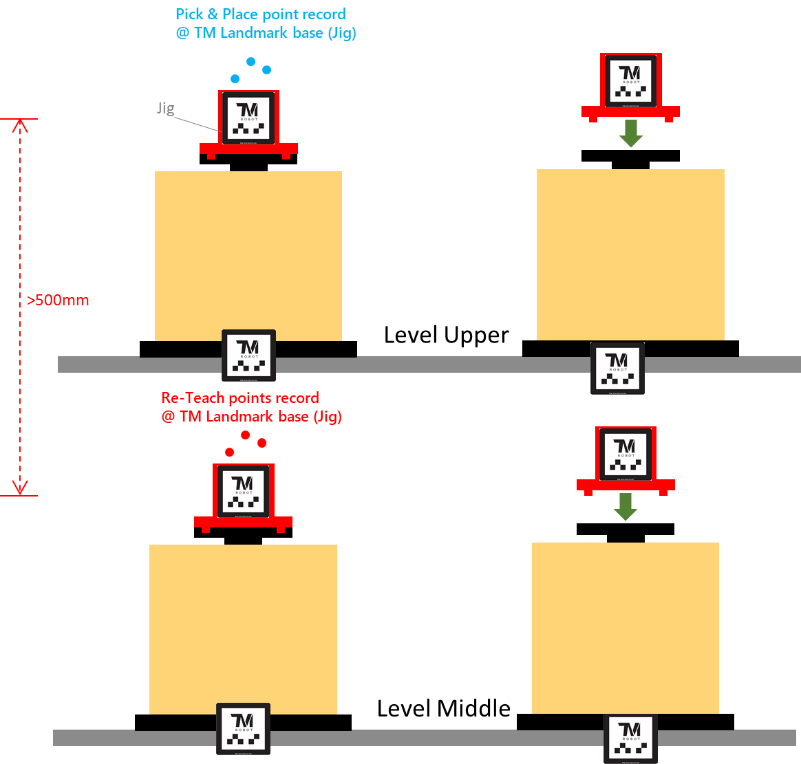
Q. Are there any limitations when applying this method?
A. If the distance between FOUP Bases is too large, differences in the robot’s posture may still introduce nonlinear errors, even when unified pick-and-place points are established through the Jig LM. As a general guideline, if the distance exceeds 500 mm, a new set of pick-and-place points should be taught.