此功能適用於:
TMflow 軟體版本: 2.24或以上版本
TMflow Simulator限定
目的 #
- 提供使用CAD模型建立虛擬環境的功能
- 提供驗證手臂與環境工作範圍的功能
TMscene相關的TMflow功能 #
匯入/匯出: 匯入CAD模型至TMscene
工具精靈: 使用CAD模型建立工具
TMscene功能 #
場景建立: 使用CAD模型建立一個虛擬場景
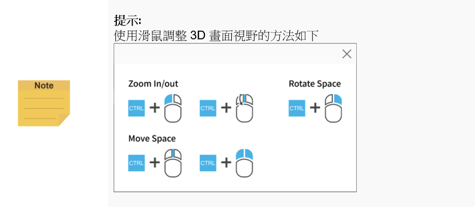
視角切換: 視野切換操作
碰撞偵測: 碰撞偵測以避免在真實場域發生
點位編輯: 可視化界面快速調整手臂點位

如何使用 #
- 匯入CAD模型檔案至TMflow Simulator
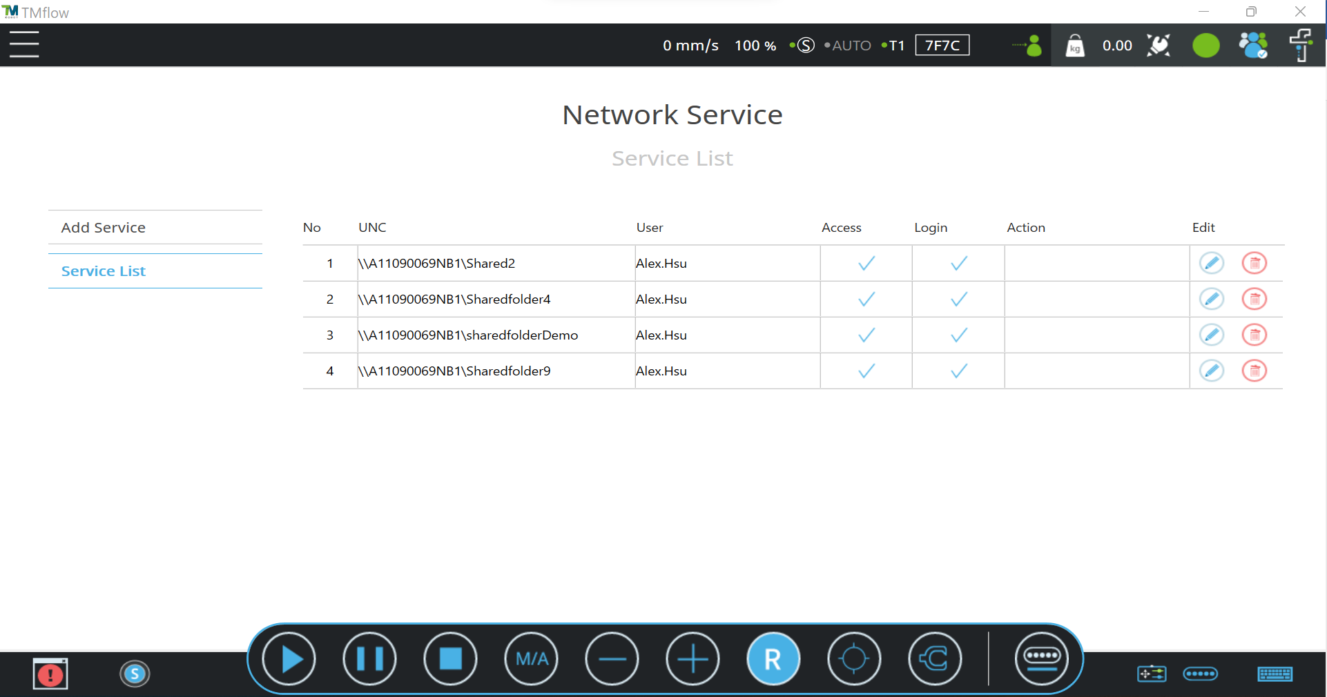
a. 建立一個共享資料夾或使用USB裝置
- 請參考”Software Manual TMflow_SW2.24″的5.6.2.1或5.6.2.4章節建立共享資料夾或是使用USB裝置。展示中使用共享資料夾建立網路服務。
b. 將CAD模型檔案放至新建立的資料夾
範例中的資料夾路徑如下:
D:\TMsceneDemoFile\sharedfolderDemo (共享資料夾名稱)\TM_Export\A11090069NB1 (裝置名稱)\TMScene\Step
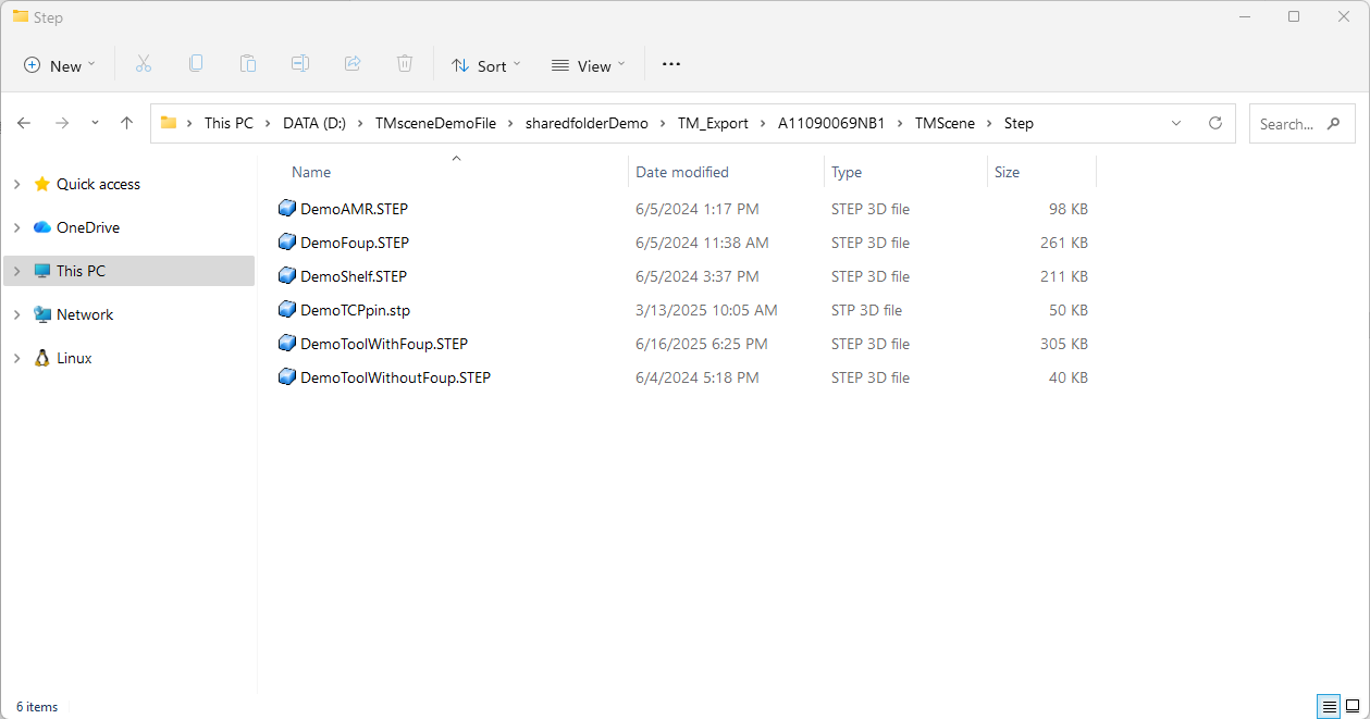
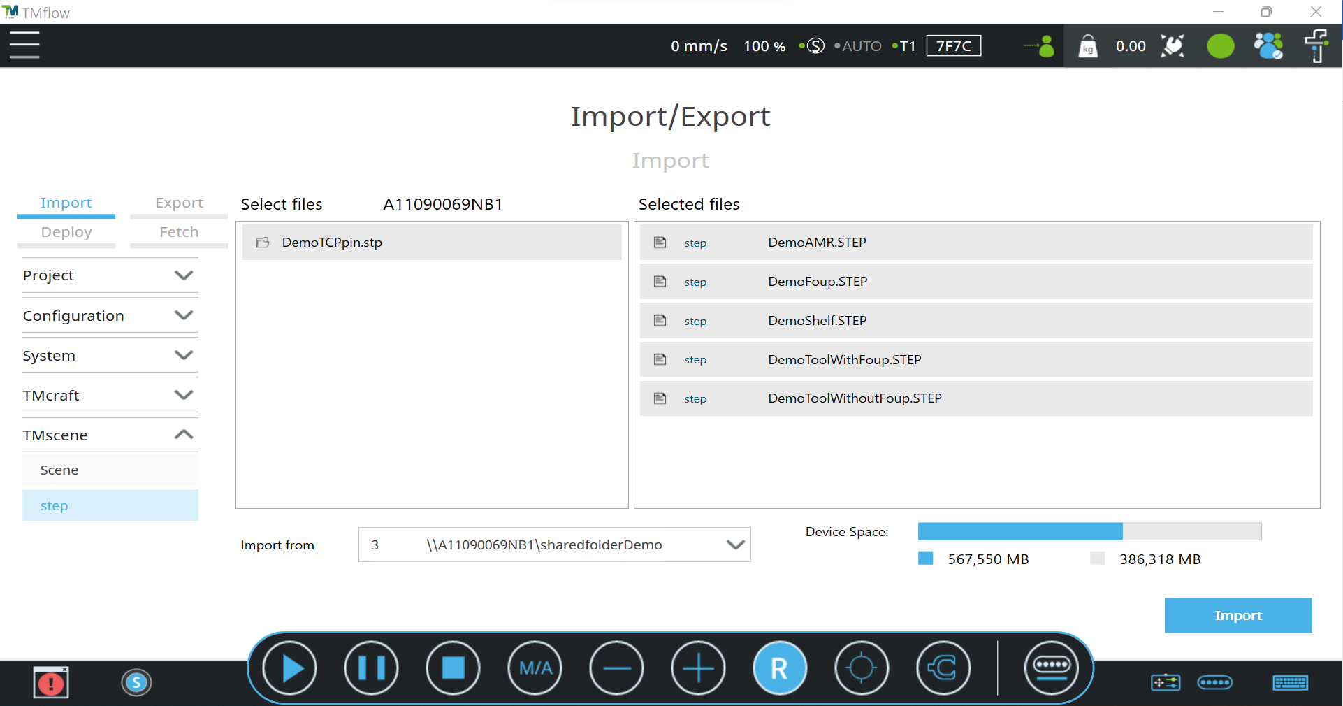
c. 使用匯入/匯出功能將CAD模型檔案匯入至TMflow
將展示CAD模型檔案匯入TMflow
2. 工具CAD設定
工具設定中的工具精靈 (選單 > 配置 > 工具設定 > 工具CAD設定) 可以讓使用者使用CAD模型定義工具中心點
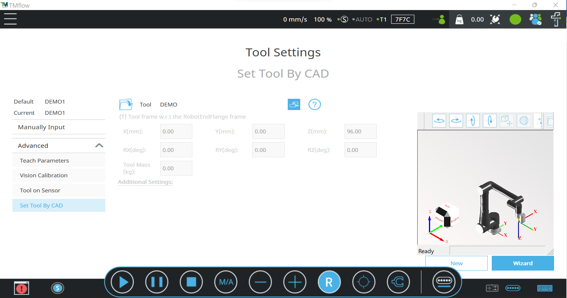

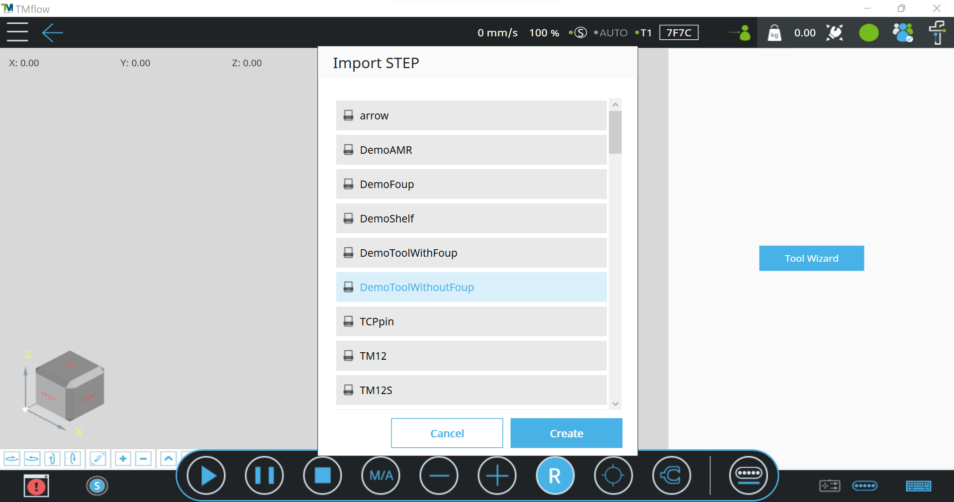
a. 選擇CAD模型
選擇工具的CAD檔案。
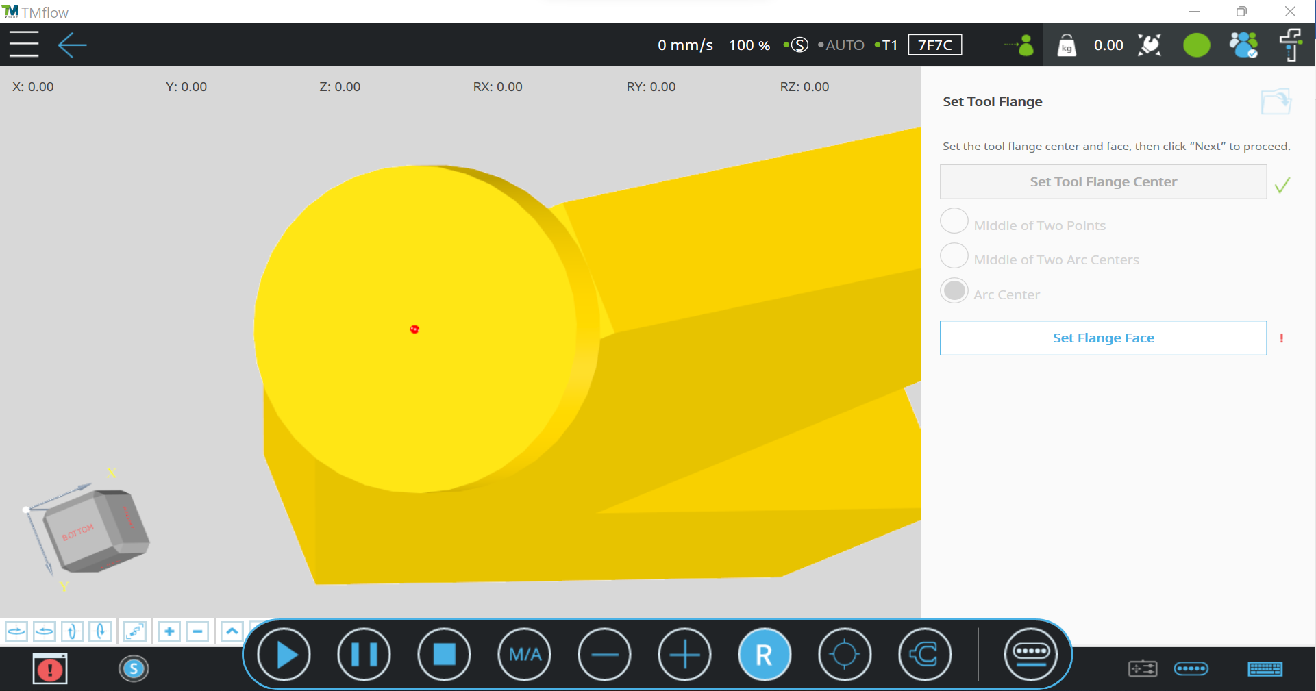
b. 設定工具法蘭
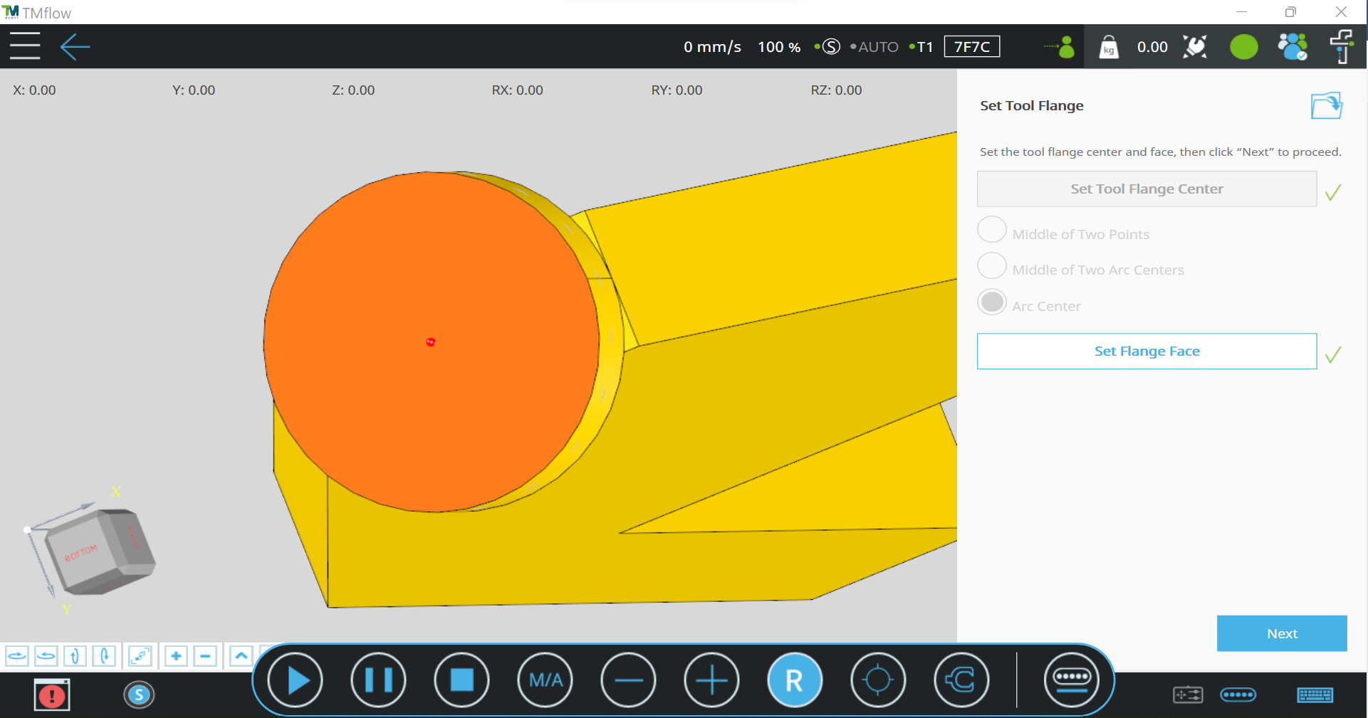
首先在CAD模型上設定法蘭中心點,有三種方法可以設定法蘭中心點,分別為兩點中點、兩圓弧中心中點、圓弧中心。範例中使用圓弧中心點來設定法蘭中心點。
接下來在CAD模型上選擇法蘭平面
c. 設定法蘭偏移
假設CAD模型以錯誤的旋轉角度裝上手臂或是有轉接板的需求,可以在這個步驟使用偏移或旋轉。若無上述需求,可以直接點擊下一步繼續。範例中並無使用法藍偏移。

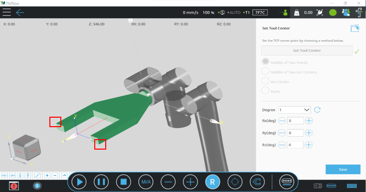
d. 設定工具中心點
在CAD模型上選擇工具中心點。有四種方式可以選擇,範例中使用兩點中點來達成。工具中心點位置選擇完成後,可以在UI上調整旋轉角度。範例中沒有調整旋轉角度。當所有設定完成後儲存工具以完成設定。當前工具被設定為該工具時CAD模型會顯示在3D畫面中。
3. 建立虛擬場景
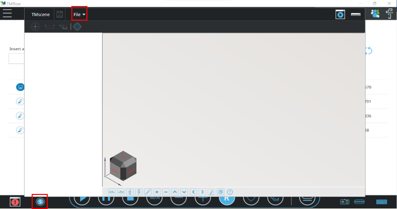
點擊TMflow Simulator介面中左下角的圖示開啟TMscene。新增或開啟場景功能在TMscene介面左上方的檔案中。
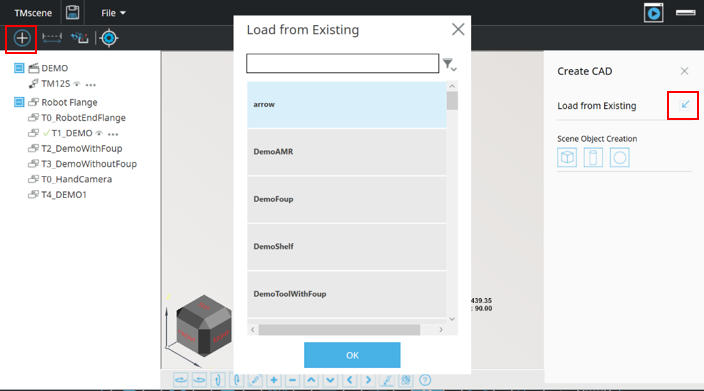
a. 新增CAD模型至虛擬場景
選擇的CAD模型會生成在虛擬場景的原點。除此之外,長方體、圓柱體、圓球體可以直接透過介面生成在虛擬環境中。
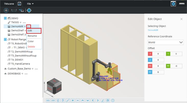
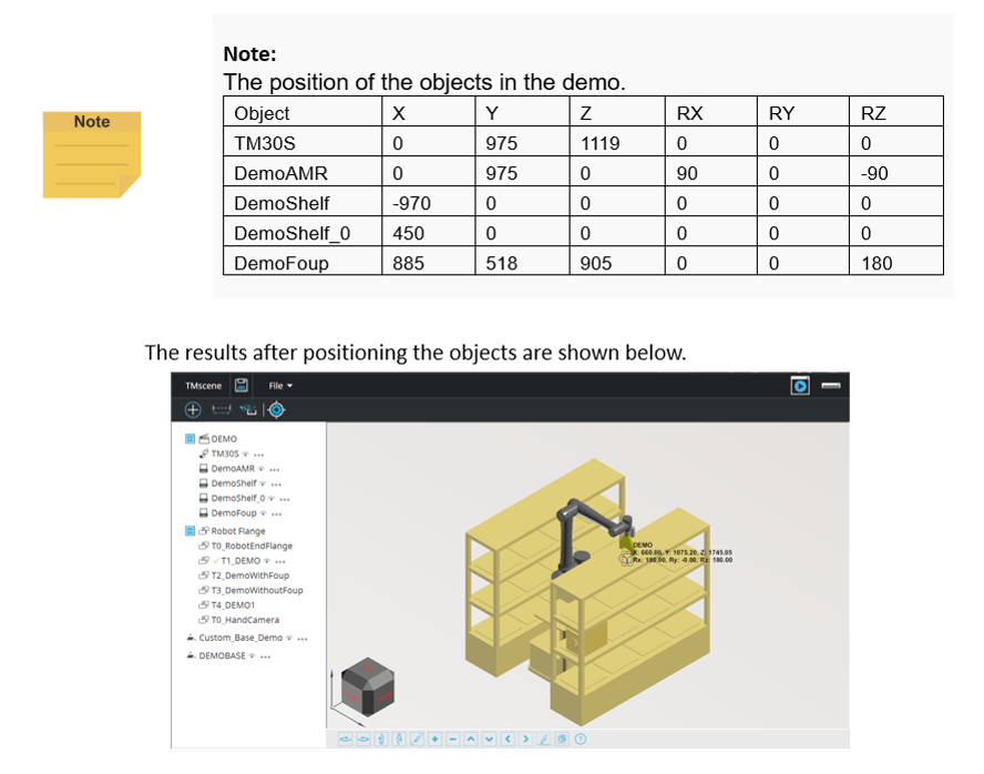
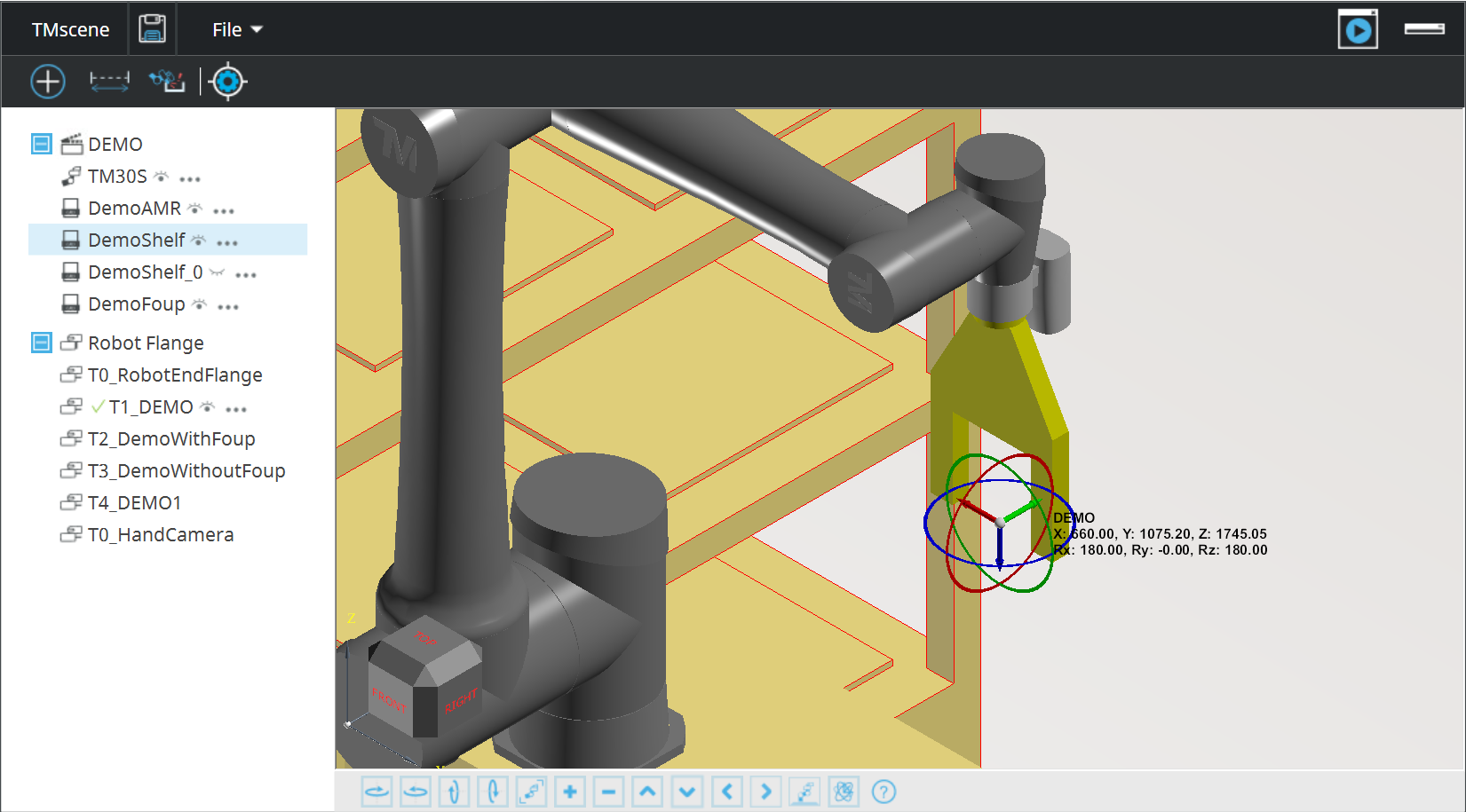
b. 建立虛擬環境
使用物件選單中的編輯功能移動TMscene中的物件。編輯介面會顯示在TMscene視窗的右側。同時,一個拖拉球會出現在物件的原點。拖動物件或是直接輸入物件座標來調整物件的位置。
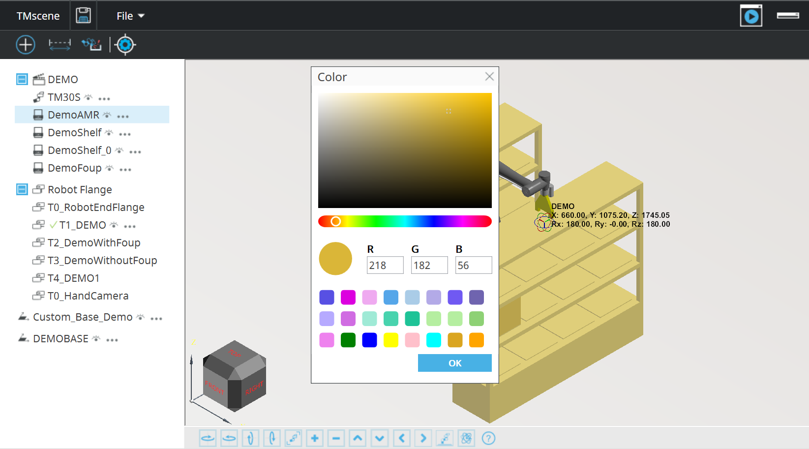
c. 調整物件顏色
物件選單中的顏色可以改變物件的顏色
4. 編程手臂專案
在虛擬環境建立完成後,可以開始編程手臂專案
a. 手臂控制
除了原本TMflow Simulator中的手臂控制,有兩種額外的方式可以控制虛擬手臂:
第一種為使用拖拉球拖動手臂。當FreeBot可以被使用時,拖拉球會在工具中心點上顯示。
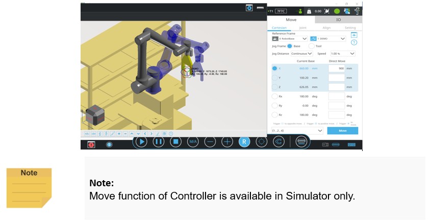
第二種為控制器中的移動功能。當控制器中的數值被填入後,一個以目標位置姿態的示意手臂會在TMscene中顯示。點擊移動會將手臂移動至目標位置。目標位置的Robot Configuration也可以在介面上設定。
b. 點位教導
結合前述的兩種移動手臂的方法,點位可以在手臂移動到正確位置後加入專案中。
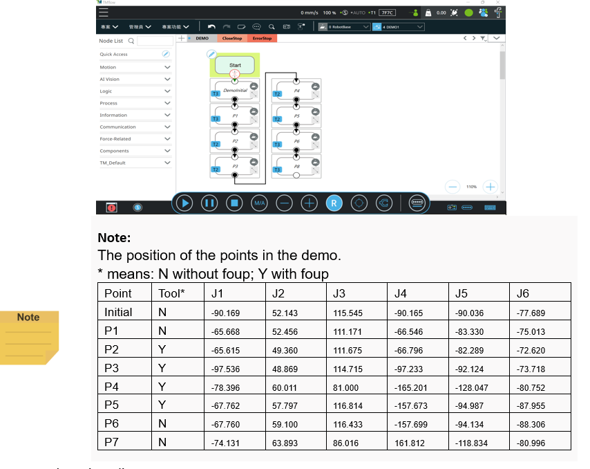
c. 專案編輯
將手臂點位依序串接,並且將所有點位設定為直線模式
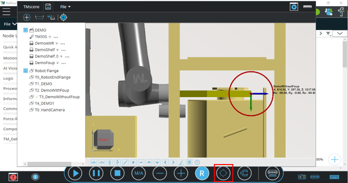
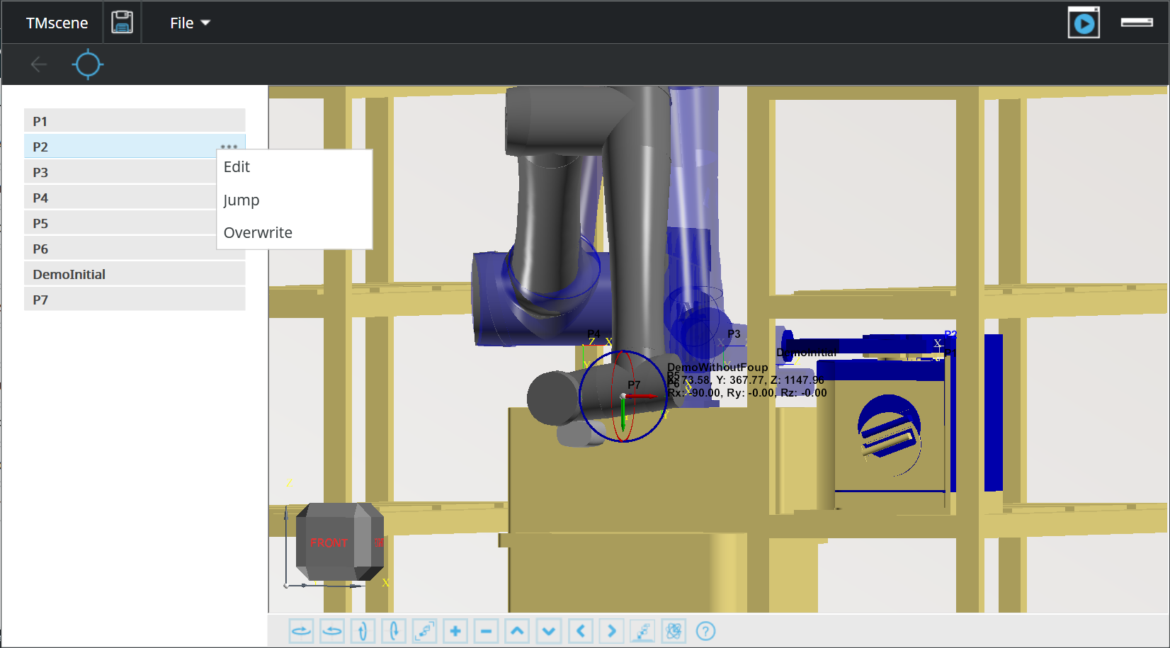
d. 點位編輯
在點位編輯模式中,你可以在虛擬環境中檢視每個手臂點位的位置。使用介面中的圖示進入點位編輯模式並且檢查點位。
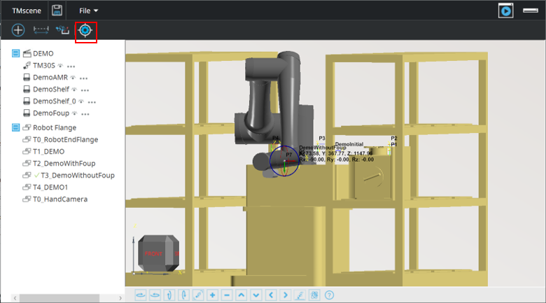
從TMflow專案的點位會被顯示在TMscene視窗左側。每當點位被選擇,示意手臂會顯示該點位的位置。使用點位選單內的跳點會將手臂移動到該點位。
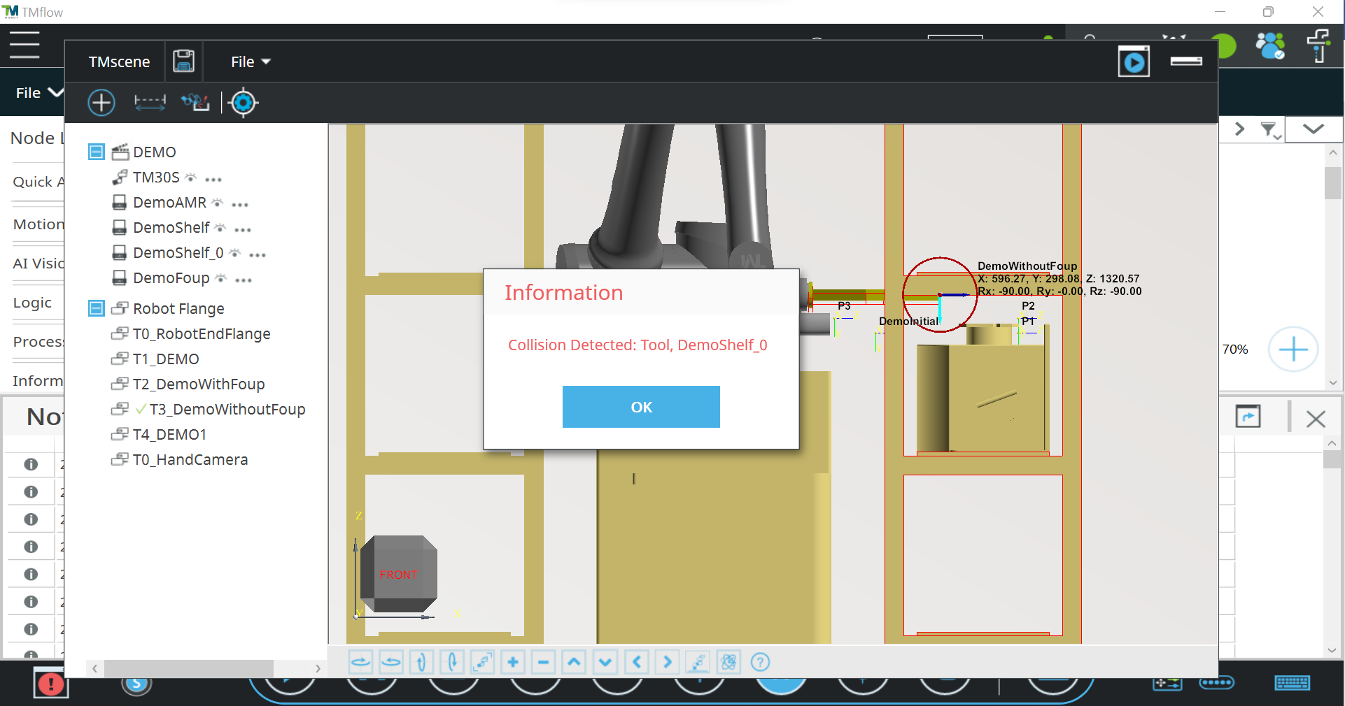
5. 碰撞偵測
為了確保手臂的運行期間沒有與周遭環境碰撞,請使用碰撞偵測功能並運行專案。
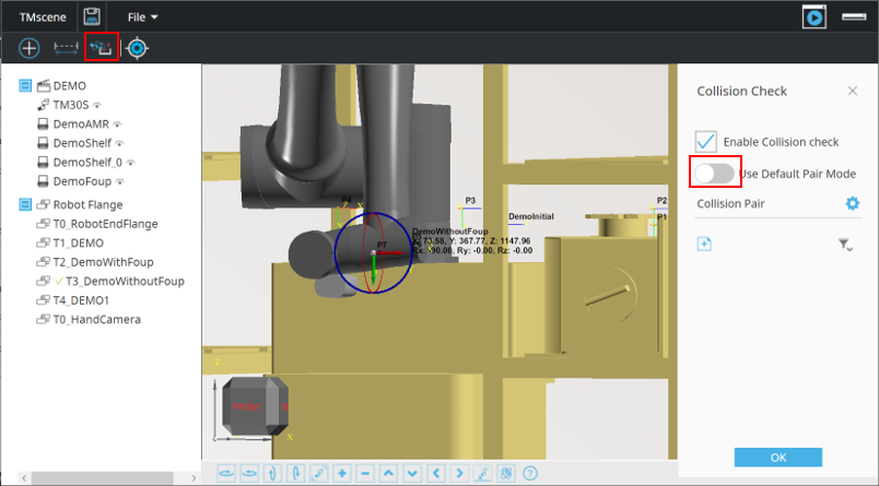
在此範例中,我們建議使用預設碰撞對模式。當預設碰狀對模式被啟用後點擊確認按鈕後,所有碰撞都會被偵測。若想使用手動設定,請參考TMflow軟體手冊。
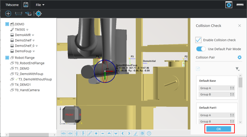
所有的碰撞會自動停止手臂專案,接著會跳出一個碰撞物件提示並且會標示在虛擬環境中。