Examples are valid for:
TMflow Software version: 1.76.6300 or above.
TM Robot Hardware version: All versions.
Note that older or newer software versions may have different results.
Compliance Node Explanation #
The Compliance node can set the force limit on the robot movement along a single axis. This setting can be used for various applications of collision testing, object assembly, and object searching. Users can determine the direction of robot motion based on the Tool or the Base.
The compliance settings of the Node comes with: Single Axis, Teach, and Advanced. Refer to the example description in this Section for single axis. For teaching, the Compliance node can choose to teach with line direction or rotation direction. Users can use the two points of teaching to perform relative movement to complete the assembly, collision and other jobs. After setting the relevant parameters, users can specify the speed of motion and other additional stop conditions in the motion mode, to ensure that the tool will not be damaged. In the Compliance mode, the safety settings still function.
Compliance Node – Single Axis #
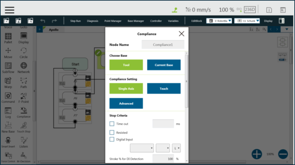
- Choose Base: Select Tool or Current Base, and click OK to have the robot move accordingly
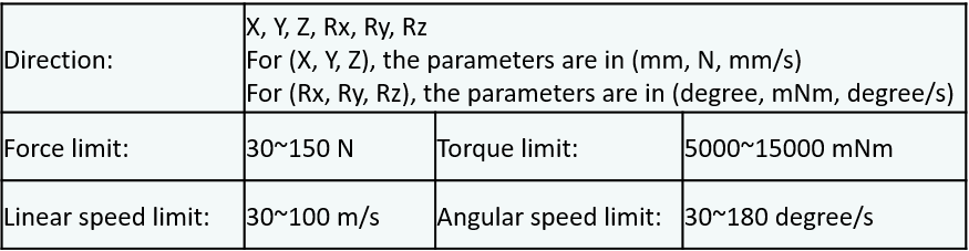
- Compliance Setting: Select Single Axis to define the direction (axis), distance, target force/Torque, speed of the compliance, Teach to use manual teaching method, or Advanced to define force/torque, distance limit, and target speed for applicable directions of the compliance.
- Stop Criteria:
- Timeout: This node will be released if the set time is reached before or while running the job
- Resisted: When the resistance is sensed, the speed at the robot end is close to zero, and the node is released
- Digital Input: Set a digital input signal to release this node once a specific DI is triggered
- Stroke % for DI Detection: Applicable to Single Axis and Teach. Detects DI along the moving distance in the single axis. Stops and outputs the variable with Error (6) if DI is detected below the stroke percentage. Stops and outputs the variable with IO Triggered (4) if DI is detected above the stroke percentage.
- Analog Input: Set an analog input signal, when met, this node is released
- Others :
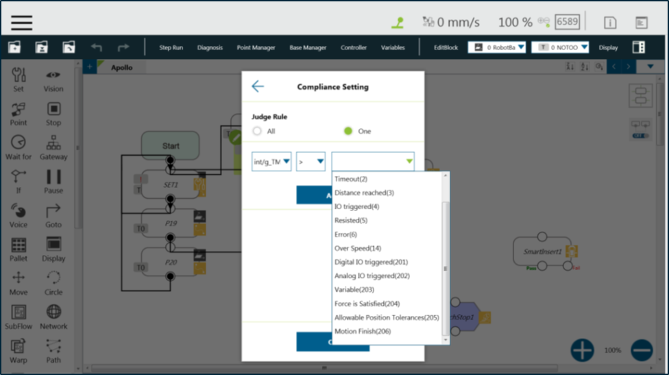
Output Variable: An int variable can be used to show the result of the Compliance, meaning which criteria has been triggered in the first place, and should have the following possibilities:
- –
- Timeout
- Distance Reach
- Digital Input (or Analog Input) triggered after the Stroke
- Resisted
- ERROR (including TCP speed over limit, incorrect timing of DI triggered, and etc.)
14: Over Speed
- Change payload to: Define the payload on TCP if any payload existed
- Compliance Duration when Stop: Set the length of the time to switch between force control and position control. Defaults to 200, the value is valid between 0 and 1000 as an integer and supports the variable setting.
- Resistance on non-target motion direction: Reduce the vibration of the robot. Set to High Resistance for applications with great reactions against the robot TCP.
- Test: Test the performance. The robot will actually start moving at 3% of project speed when this button is pressed.
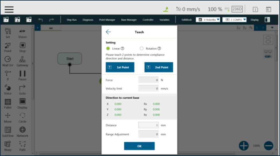
Compliance Node – Teach #
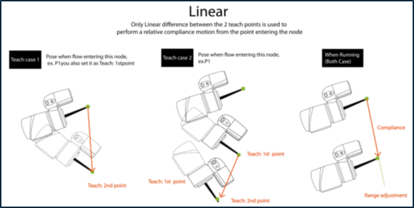
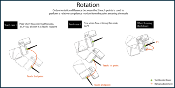
- Teaching setting: Teach in a line direction or rotation direction. Refer to the figures below for details.
- Teaching Point: Set two points and calculate the direction and distance. The two points are not the actual recorded points, and the movement method is relative movement similar to the Move node.
- Range Adjustment: Provide Users with direct adjustment of distance or angle in the original direction without resetting the teaching point.
- Users can pre-program the solution for any possible situation according to the result of Variable returned by the Compliance node, and coordinated with the IF node.