Table of Contents
This article is applicable under the following conditions:
TMflow version: 1.76.6300 or later
TM Robot hardware version: All
Please note that, depending on the TMflow version, the user interface and the operation procedure may differ.
When to do calibration #
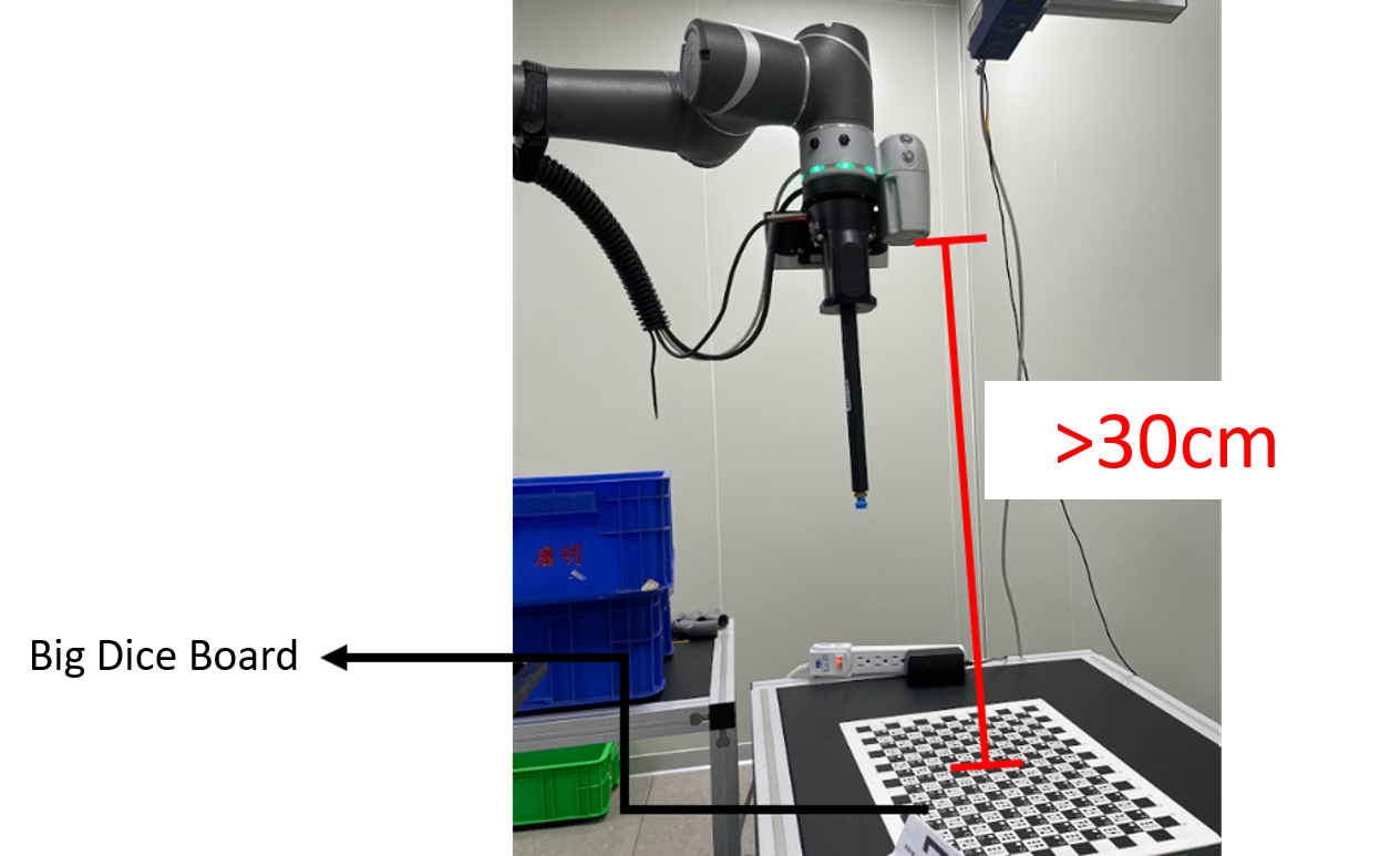
- Large and small calibration plates are both used to create a workspace during fixed positioning. If any of the calibration plates is > 30 km away from the camera, causing the camera to produce a low-resolution image of the plate, then the plate cannot be clearly identified. This prevents the user from calibrating the workspace correctly.
- Object-based calibration is applicable to the eye-in-hand (EIH) setup only, which employs the difference in the robot servoing movement to calculate the relative relationship between the object and the TM Robot, eliminating the need to create a workspace.
- An object for calibration that has a definite shape and lacks symmetry is easier to position accurately.
Causes of failure to create a workspace #
- The working distance is > 30 cm.
- If the camera’s resolutions are set to 1280×920, it produces low-resolution images.
- If the TM Robot cannot find all points on the calibration plate, click the video link below to check out how this problem can be solved through object-based calibration.
Tilt correction #
- Setup:
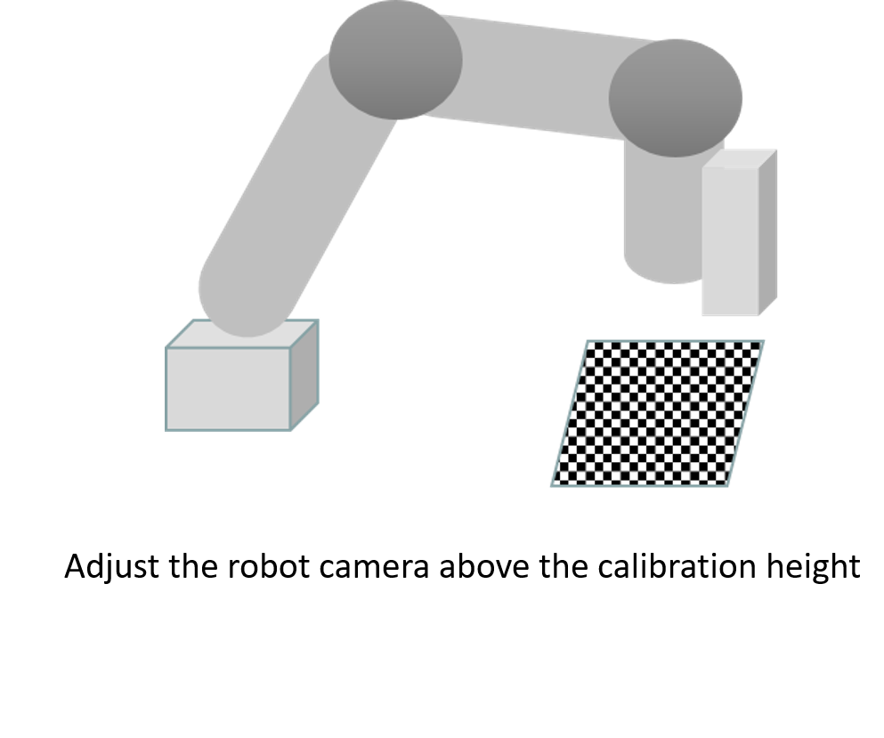
- If the working distance is large, the TM Robot cannot find the calibration plate when calibrating a workspace.
- In this case, manipulate the robot to a distance where it can find the calibration plate.
- Create a vision job
- Select the EIH 2D camera of the robot
-
- Open Camera Kit.
- Set the camera’s parameters and select an appropriate focus value.


-
- Click Tilt Correction

- Click Tilt Correction
- Enter the UI for Tilt Correction
- Make sure the camera and the workspace are aligned
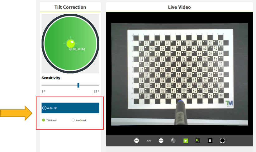
- Execute tilt correction using a supplied calibration plate.
- Select TM-Board and click Auto-Tilt.
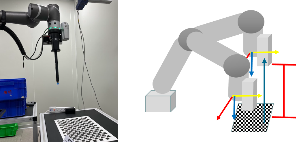
- Lifting the robot to the working distance
- Manipulate the robot along the z-axis direction of the tool base to the working distance.
Editing the vision flow #
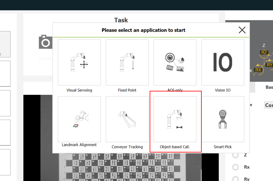
- Select Object-based Cali.
- Enter the editing process for the vision flow.
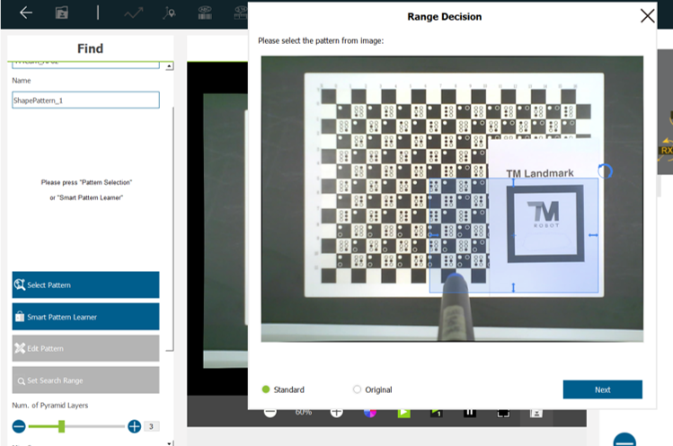
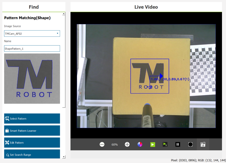
- Pattern matching(shape)
- Click Find > Pattern Matching(shape).

-
-
- Place distinguishable and target objects at the same height as the same workspace.
- The distinguishable object should be matched with objects with visible shapes; the features obtained through this matching are directional.
- The example below displays a magnified TM Landmark as a distinguishable object.
-
-
-
- Acquire the edges of TM Landmark and the characters printed on the landmark, and ensure its directionality.
-
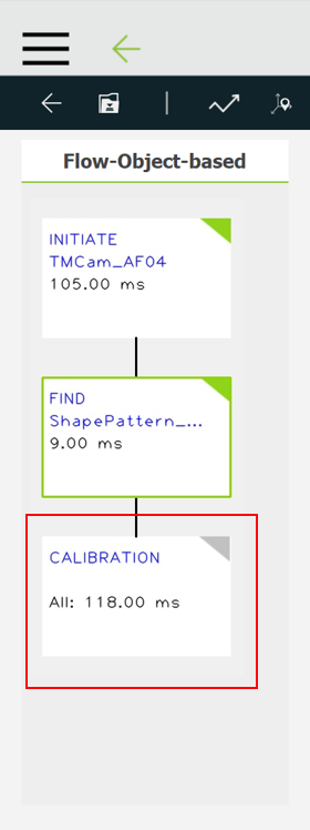
- Calibration
- Finish the Find process and go to Calibration.
-
-
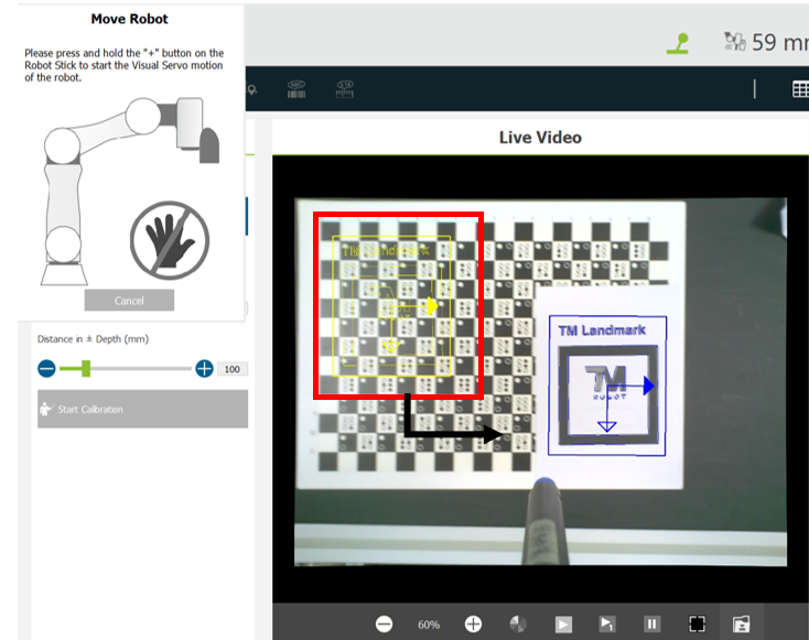
- Select an appropriate movement range.
- If the movement range is too small, the system may send a warning “Over the servoing limit.”
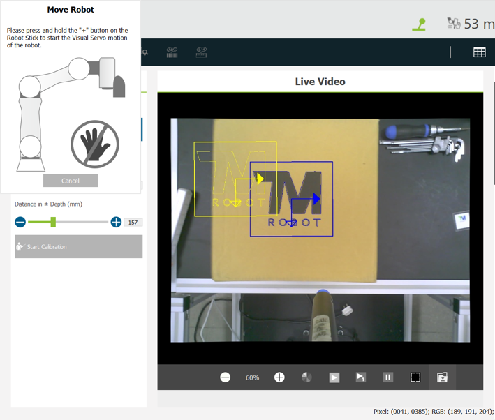
- After the settings are completed, move the TM Robot to its initial position. Then click Start Calibration.
- The robot moves to five different positions during calibration.
- Hold the + button on the robot stick until the calibration is finished. This prevents the robot from colliding with any obstacles while on the move.
- If the features matched are not clear enough, the yellow-colored scope of the actual object sampled becomes inaccurate, as shown in the image below. In this case, make necessary changes in the Find module.
-
- Acquire the object’s base
- After the vision flow is edited, execute the flow to obtain the robot base relative to the object—that is, the workspace of the target object.
- Go back to the Find module, check the target object, and edit the flow for the object.
Troubleshooting #
-
- Issue:
- If the TM Robot keeps failing to match an object’s features while it is servoing the object during calibration, a dialog box will appear as follows:
- Issue:

-
- Solutions:
- Check whether the features matched are too sophisticated. Then go back to the Pattern Matching process and remove any feature that is difficult to match on the pattern matched.
- Use an Enhance module to make any to-be-matched feature more visible and easier to find.
- Set a lower score in the Find module. If the pattern is symmetrical, impose a limit on the angle for finding the pattern.
- Solutions:
Demo with cardboard #
- Setup:
- Object-based calibration is performed using the logo “TMROBOT” printed on the top of a piece of cardboard. Then a flow is edited in ways that manipulate the TM Robot to use a suction nozzle to pick up the cardboard.
- Tools:
- Cardboard with a “TMROBOT” logo printed on it

- ROBOTIQ Epick Gripper

- Cardboard with a “TMROBOT” logo printed on it
- Workspace
- Decide the distance between the camera and cardboard
- The distance between the camera and cardboard is about 40 cm.
- The workspace cannot be calibrated through fixed positioning.
- Execute object-based calibration to obtain the position of the cardboard

- Editing the vision flow
- Open Camera Kit
- Set the camera’s parameters and focus.
- Place a calibration plate and do tilt correction.
- Select Pattern Matching(shape).
- Circle the TMROBOT logo at the center of the cardboard and the shape of the cardboard.
- Open Camera Kit
-
-
- Do calibration
- Set the movement range.
- Start calibration.
- Do calibration
-
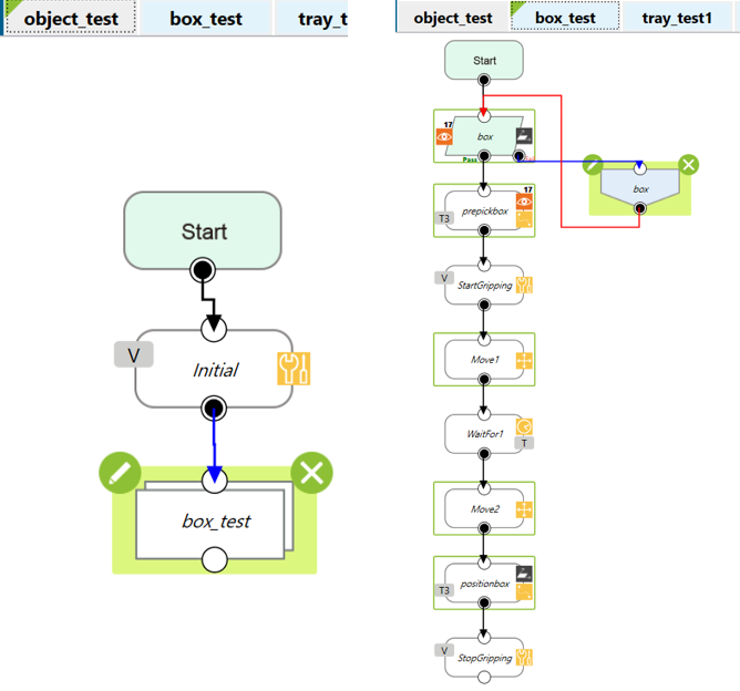
- Editing the flow
- Use a vision job to find the cardboard.
- Teach the robot where to pick up the cardboard and install a suction nozzle for the robot to fetch the object.
- Results
- The robot finds the cardboard and arrives at its center.
- The robot uses the suction nozzle to pick up the cardboard.
- Demo Video
Demo with SSDs #
- Setup:
- Several SSD are placed on their respective trays, object-based calibration performed using the words printed on the top of the SSDs and the shape of the drives, and the TM Robot is manipulated to use a suction nozzle to pick up the drives.
- Tools:
- SSD
- ROBOTIQ Epick Gripper
- SSD
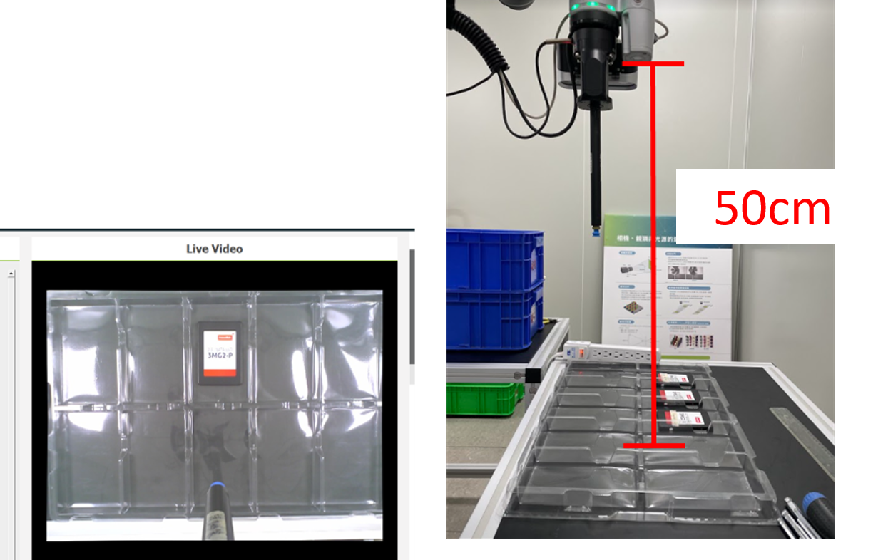
- Workspace
- Set up a workspace for the SSDs.
- The distance between the camera and trays is about 50 cm, so the trays can be entirely seen by the camera.
- The workspace cannot be calibrated through fixed positioning.
- Execute object-based calibration to obtain the positions of the SSDs.
- Editing the vision flow
- Open Camera Kit
- Set the camera’s parameters and focus.
- Place a calibration plate and execute tilt correction.
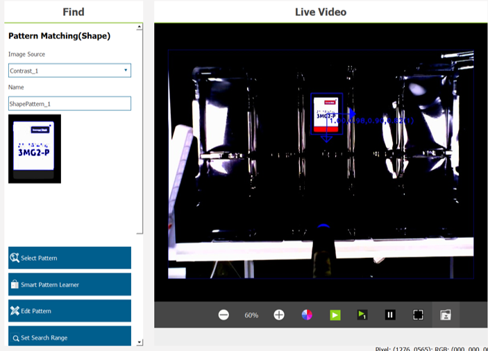
- Use an Enhance module to make the SSDs more identifiable.
- Use Pattern Matching(shape) to circle the words printed on their center and the shape of the drives.
- Open Camera Kit
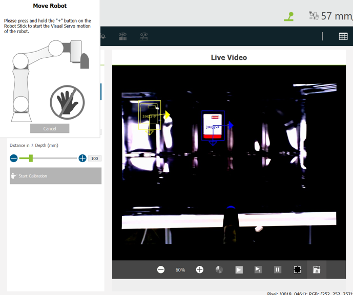
- Do calibration
- Set the movement range
- Start calibration
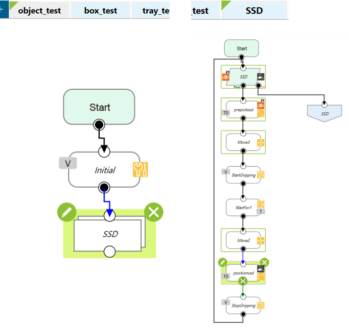
- Editing the flow
- Use a vision job to find the SSDs.
- Teach the robot where to pick up the SSDs and install a suction nozzle for the robot to fetch the objects.
- Results
- The robot finds the SSDs and arrives at their center.
- The robot uses the suction nozzle to pick up the SSDs one after another from the trays.
- Demo Video


