Examples are valid for :
TMflow Software Version: All versions
TMflow Robot Hardware Version : All versions
Other Specific Requiremnets : None
Note that older or latest software versions may have different results.
How to Use the Compliance Node #
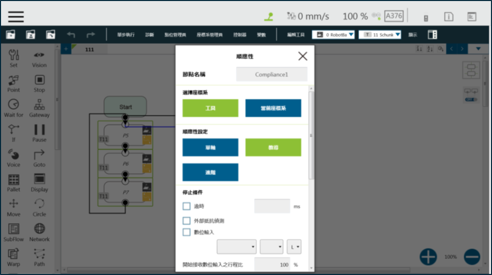
The Compliance node allows you to set a force limit on the robot movement along a single axis, so you can perform collision testing, object assembly, or object searching. You can decide the direction of robot motion by using Tool or Base.
Compliance Settings include Single Axis and Teach. An example for Single Axis is provided in the next section. As for Teach, you can choose to teach with either direction—Linear or Rotation—and use the two points of teaching to perform relative movement to complete a job, such as assembly or collision. When you’re done making Compliance settings, specify the speed of motion and any Stop Criterion in the motion mode. This ensures that the tool will not be damaged. In the Compliance mode, the safety settings still apply.
Using Compliance : Single Axis #
- Choose Base: Select Tool or Current Base to have the robot move accordingly.
- Compliance Settings: Select
a) Single Axis to define the direction (axis), distance, target force/torque, and compliance speed;
b) Teach to execute the manual teaching method; or
c) Advanced to define force/torque, distance limit, and target speed for the applicable directions of compliance.
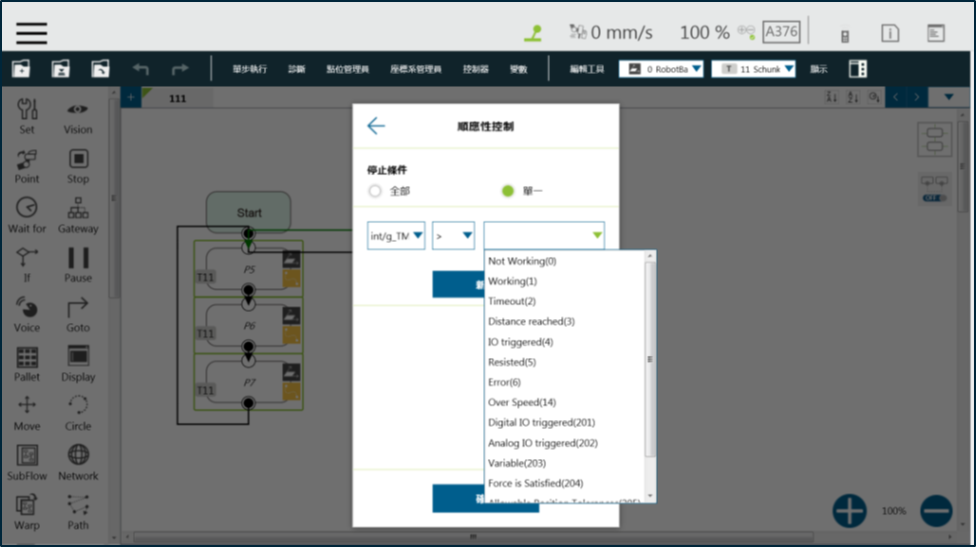
Set Stop Criteria:
- Timeout: This node will be released if the set time is reached before or while executing the job.
- Resisted: When resistance is detected, the speed at the robot end is close to zero, and the node is released.
- Digital Input: Set a digital input signal, and once the criterion is met, this node is released.
- Stroke % for DI Detection: Applicable in Single Axis and Teach. DI detection is performed when the moving distance in the single axis exceeds the stroke %. A variable with IO Triggered (4) is output if DI is detected, or a variable with Error (6) if not.
- Output Variable: A variable for setting Stroke % for DI Detection. This variable can be used to show the Compliance result, indicating which criteria have been triggered in the first place and should have the following possibilities:
- –
- Timeout
- Distance Reach
- Digital Input (or Analog Input) triggered after the Stroke %
- Resisted
- ERROR (including TCP speed over limit, incorrect timing of DI triggered, and etc.)

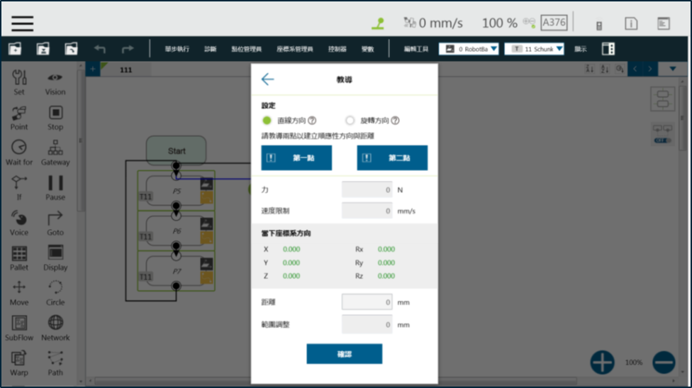
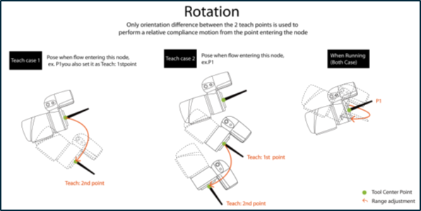
Using Compliance : Teach #
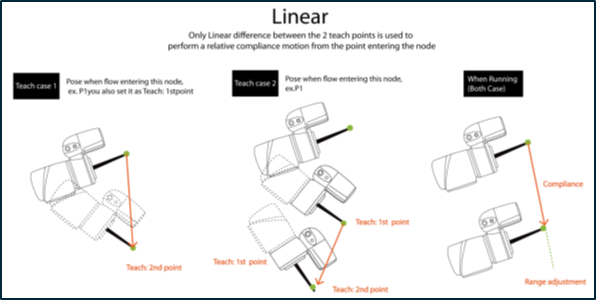
- Setting: Choose Linear or Rotation to teach.
- Teach Point: Set the two points and calculate compliance direction and distance. The two points are not any actual recorded points, and the movement performed is the relative movement, which is similar to the Move node.
- Range Adjustment: This allows you to change the distance or angle in the original direction without having to reset the teaching point.
For any possible situation, you can pre-program a solution that takes into account the results of variables returned by the Compliance node, and works with the IF node.