Background Story #
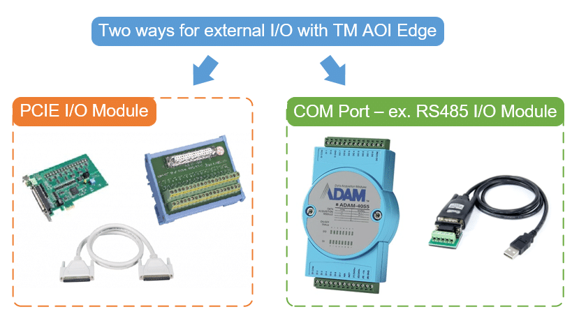
There are two ways to use external I/O device with TM AOI Edge software. One is installing PCIE I/O Module on the computer. But if it’s unable to install this module on your computer, you can access I/O device through a COM Port.
Here we will use an Advantech RS485 I/O Module: ADAM-4055 to achieve I/O control.
Introduction of Example #
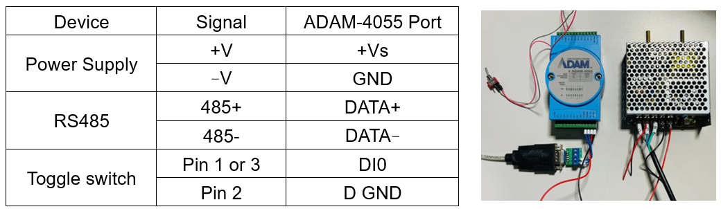
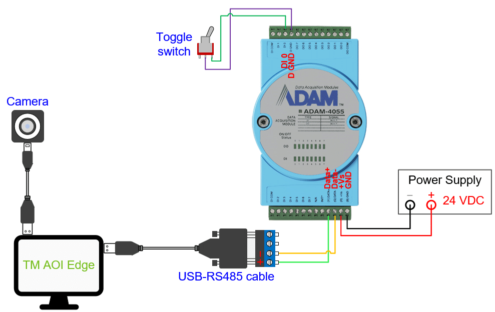
We will use an external camera to detect objects, and how to trigger the camera to photo depends on the state of the toggle switch. The pins of the switch is connected to a DI port of ADAM-4055, and signals are read in AOI Edge by using a USB-RS485 cable.
When the switch turns on which also means the connected DI port triggers, running Vision Job for object detection.
Hardware Connection and Setting #
- Hardware Requirements
-
- Advantech ADAM-4055
- 24VDC power supply
- USB-RS485 cable
- Toggle switch
- 2D camera
- Software
-
- TM AOI Edge 1.80 or above
- Camera driver
- ADAM-4055 Connection
- ADAM-4055 Settings
Do as following steps:
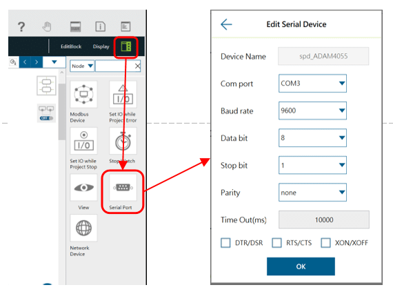
1. Add a new Serial Port and adjust the settings below.
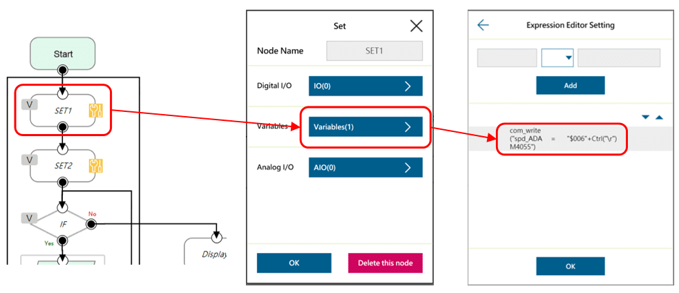
2. Add a Set Node (SET1). Use com_write() command to write data to ADAM-4055.
“$006” stands for reading DI signal. Ctrl(“\r”) stands for newline.
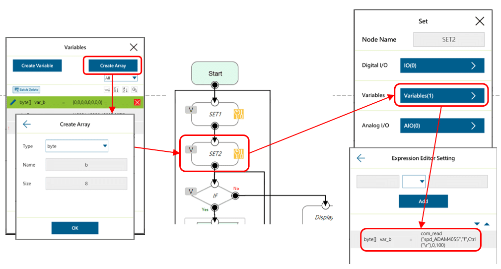
3. Create a new byte array and set size as 8. Then add a Set Node (SET2). Use com_read() command to read data from ADAM-4055.
“!” is starting symbol of Advantech product.
TMflow Project Example #
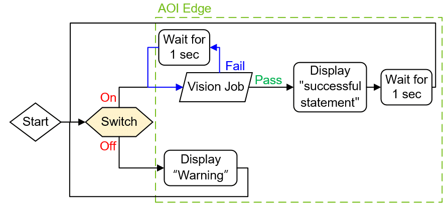
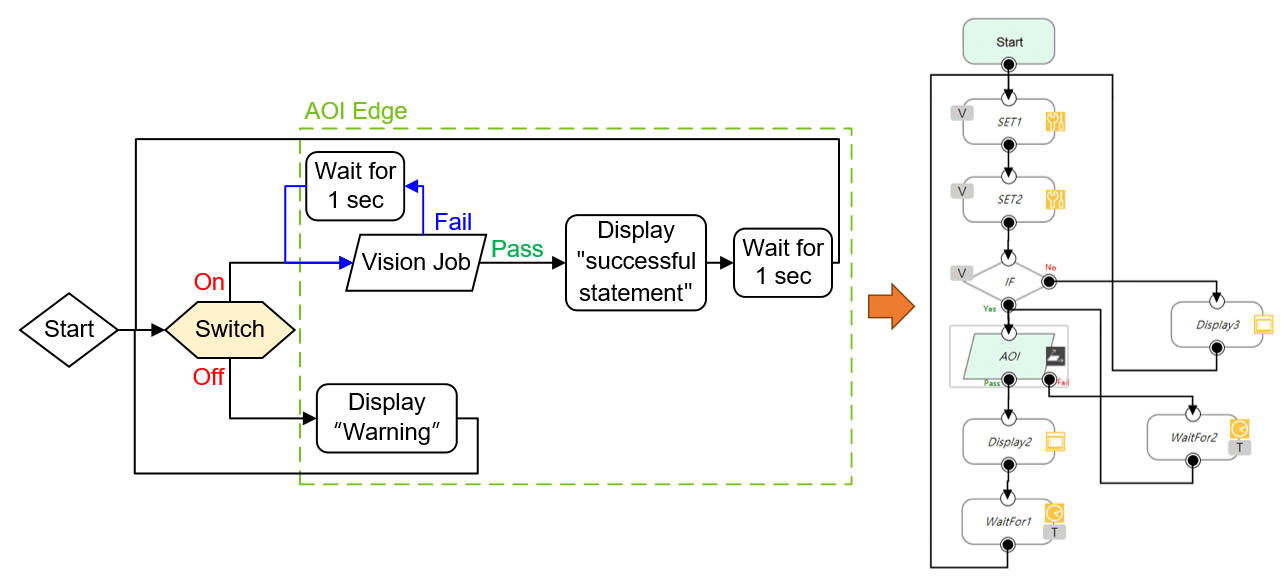
The project of the example in AOI Edge is as below.
- Steps
1. Make ADAM-4055 settings.
2. Use an IF Node to identify the state of the switch.
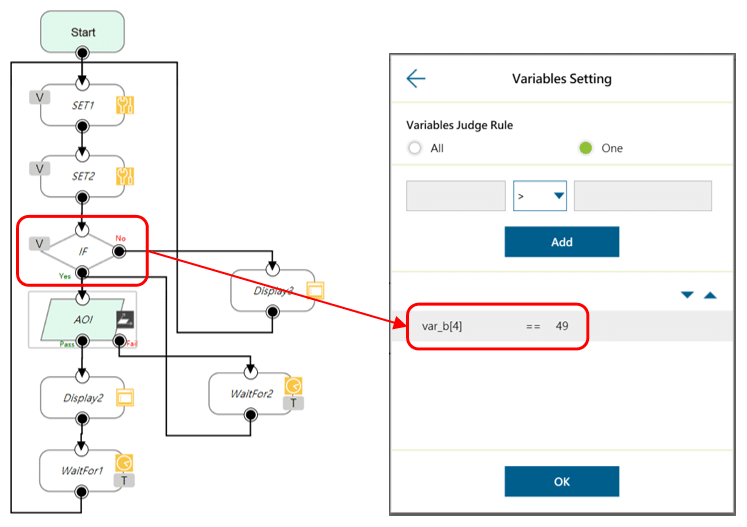
In ASCII encoding rule, number 49 in decimal system stands for Arabic number 1 while number 48 stands for 0. Besides, which DI is triggered is identified by the 3rd and 4th elements and the 1st and 2nd elements represent the address of ADAM-4055. More details in ADAM-4000 Series Manual .
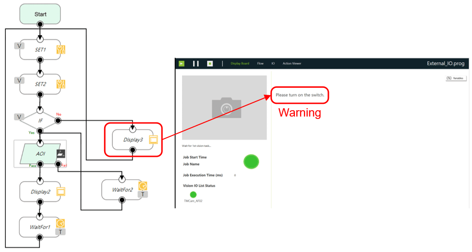
When the switch turns on (Yes path), continue running the following steps. Otherwise (No path), show warning in the Display Board and re-identify the state of the switch.
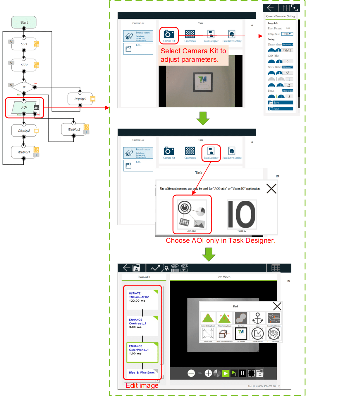
3. Add a Vision Job and make settings as below.
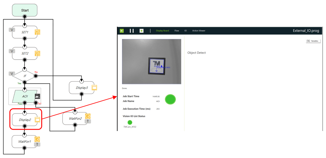
4. If the vision task is success (Pass path), show task content in the Display Board. Otherwise (Fail path), wait for 1 second and retry the vision task until success.
5. Finally, add a WaitFor Node for 1 second waiting and then repeat the whole procedures.


