Examples are valid for:
TMflow Software version: 1.76 or later.
TM Robot Hardware version: HW 1.x/2.x/3.x
Other specific requirements: Refer to Preparation section below.
Note that older or newer software versions may have different results.
Goal #
We could leverage 3rd-party module to extend the channels if additional analog ouptuts are needed.
For example, you can control the power of a welding power source from 0~100% by 0~10V.
In this article, we will demo how to set an analog output via Modbus TCP/IP in TMflow.
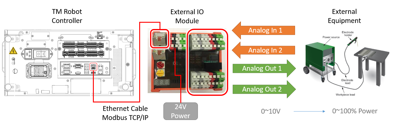
Preparation #
- TM Robot HW3.2, SW1.86
- 3rd-party IO Module – O DEAR DSNDA4Y8L-MW (4 analog output)
- Ethernet cable
- IO cables
- Load(voltage meter)
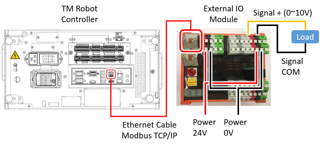
Wiring #
There is the schematic of wiring for your reference. Please refer to the website of the 3rd-party product for more information.
Setting on IO Module #
- IP – By default, it’s 192.168.1.100. Please read the manual of this product if you want to modify IP address.
- Set to 0-10V mode (red switch to #6, then yellow switch to #2)
- Do power cycle
- Set to Modbus TCP mode (red switch -> #4)
- Do power cycle
Setting on TMflow #
- IP – System > Network > IP, IP set to 192.168.1.10, Mask 255, 255, 255, 0
- Robot switch to manual mode
- Create an empty TMflow project, click Modbus Device on the panel at right hand side.
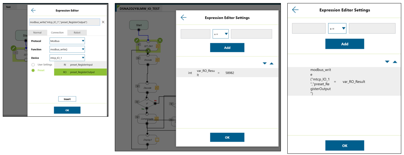
- Create an IO device with parameters such as preset_RegisterOutput
- Since the unit on IO module are in 16 bits per signal, so select Signal Type : Register Output and int16

-
Why the address is 0 on the previous step?
By the manual of IO module, address 40001 means Register Output (FC06 in the definition of Modbus).
Address 40001 means 0 of the address at TMflow side.
Address 40002 means 1 of the address at TMflow side.
|
Modbus Address on IO Device |
Address Setting on TMflow | Physical Channel on IO Device |
|
40001 |
0 |
Analog output1 |
|
40002 |
1 |
Analog output2 |
|
40003 |
2 |
Analog output3 |
| 40004 | 3 |
Analog output4 |
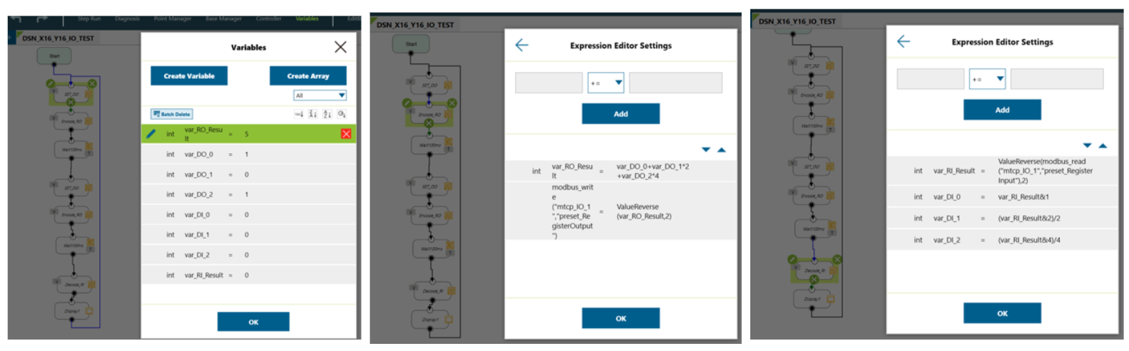
- Create a variable : int var_RO_Result.
- Create a SET node and write the Modbus address preset_RegisterOutput with var_RO_Result.
- If you want to set the phycial analog output to 9V, then the value of preset_RegisterOutput should be : 9V/10V*65536 = 58982
- If it is 5V, then preset_RegisterOutput should be : 5V/10V*65536 = 32768
| Value on Address | Physical Value |
| 0~65535 (16bits) | 0~10V |
Output Result of Analog Module #
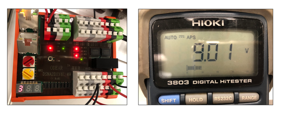
- Run the TMflow project, the physical analog output could be measured, 9V.
How to Do Linear Transformation(Input and Output Mapping)? #
From example above, we could assign a value [0~65535] to the output [0~10V].
| Value on Address | Physical Value |
| 0~65535 (16bits) | 0~10V |
But for a real welder, there will be a linear transformation between TMflow value and Welder Physical Output.
And we want those values are the same, so that it will be intuitive for user to use.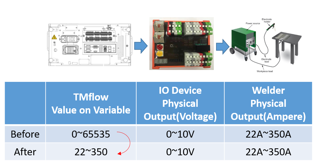
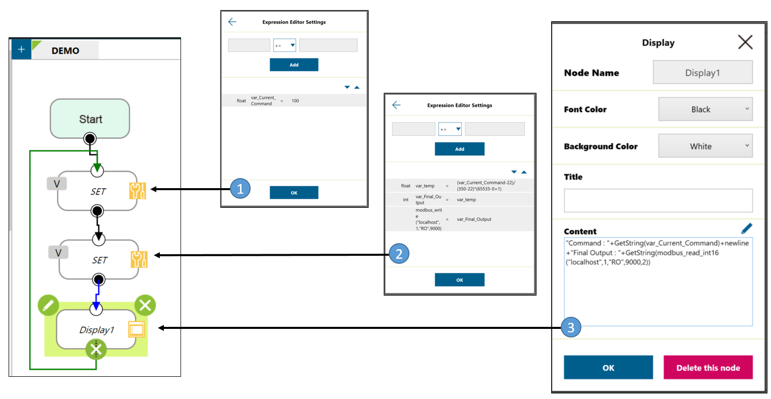
Linear transformation could be easily done in TMflow : Expression Editor, there are the steps:
- Create a TMflow project and assign a value(100A for example) to a float variable var_Current_Command
- Use the formula in Expression Editor:
(var_Current_Command-LowerLimit_Welder) / (HigherLimit_Welder–LowerLimit_Welder) * (HigherLimit_TMflow_Before–LowerLimit_TMflow_Before+1)
= (var_Current_Command-22) / (350–22) * (65535–0+1)
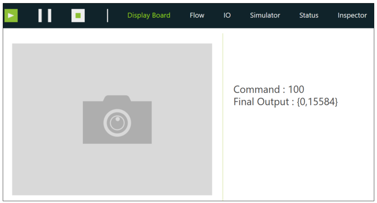
3. Show the result
After the linear trasnformation, if the command is 100A, then the value on the Modbus address will be 15584, and the physical output of welder will be:
15584/65536*(350-22)+22 = 100(A), which is the same with the command.
So we had done the linear transformation!
| TMflow Command(A) | Physical Output of Welder(A) |
| 22 | 22 |
| 100 | 100 |
| 350 | 350 |
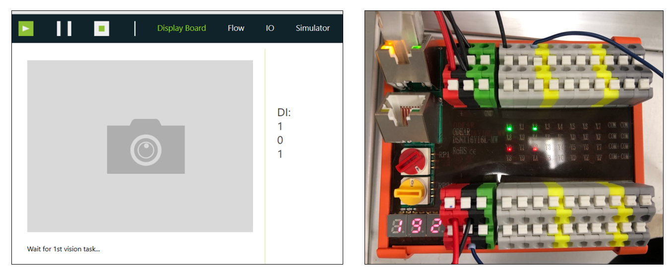
Output Result of Digital Module #
- With another IO module DSNX16Y16L-MW, TM robot could control digital input and output also.
- Create some variables in TMflow project.
- Combine the single bit value to the register preset_RegisterOutput with following expression.
preset_RegisterOutput = DO1*(2^0) + DO2*(2^1) + DO3*(2^2) + … + DO15*(2^15)
For example, if you want to set DO1 = 1(on), DO2 = 0(off), DO3 = 1(on), then preset_RegisterOutput = DO1*(2^0)+DO2*(2^1)+DO3*(2^2) = 1*1+0*2+1*4 = 6
- Add a Display node with following expression.
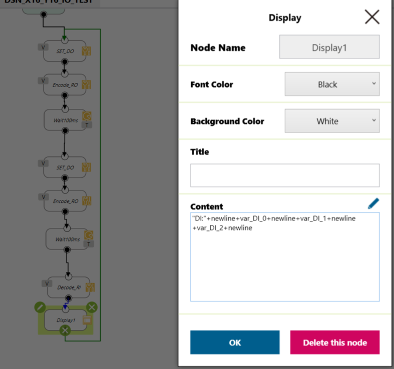
- Run the project, the status will be updated periodically.