Overview #
The TCP (Tool Center Point) is the reference point for tool interaction with the workpiece. The TCP includes six parameters: X Coordinate, Y Coordinate, Z Coordinate, Rx Coordinate, Ry Coordinate, and Rz Coordinate. The TCP is attached to the end of the robot and is referenced from the center coordinates of the flange.
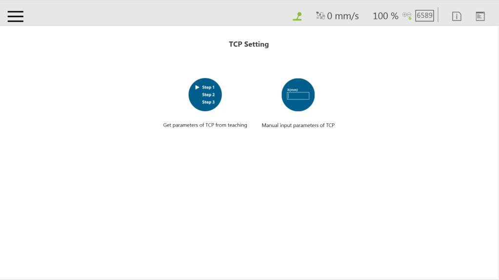
On the robot, apart from the position and orientation reference values of the six elements, the tool weights and the inertia values can also be input to compensate the performance during operation to avoid misreading the effect of the tool on the robot as an external force. The TCP Setting can be accessed from the Robot Setting page. Select the left button to create TCP from teaching.
Create Parameters of TCP with Hand Guidance Teaching #
Follow the steps to create a TCP by teaching:
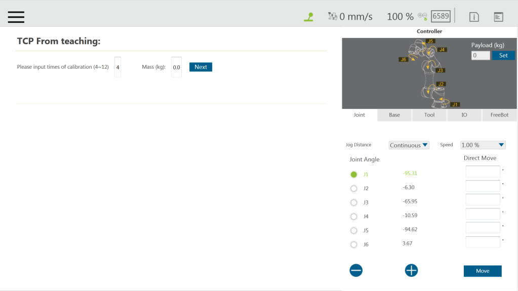
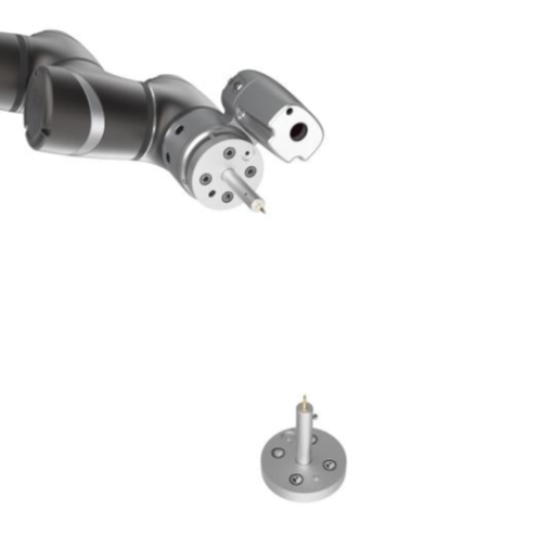
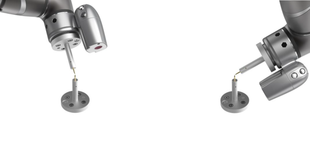
Step #1: Set the times of calibration and the mass of tools The position of the TCP is clearly marked on the tool. In this example, the tool is a Calibration Pin Set, and the TCP is located at the tip of the needle.
Step #2: Fix the Calibration Needle on a solid surface.
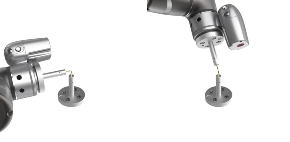
Step #3: Align the end of the tool to the calibration point by teaching, and follow by clicking the record on the screen.
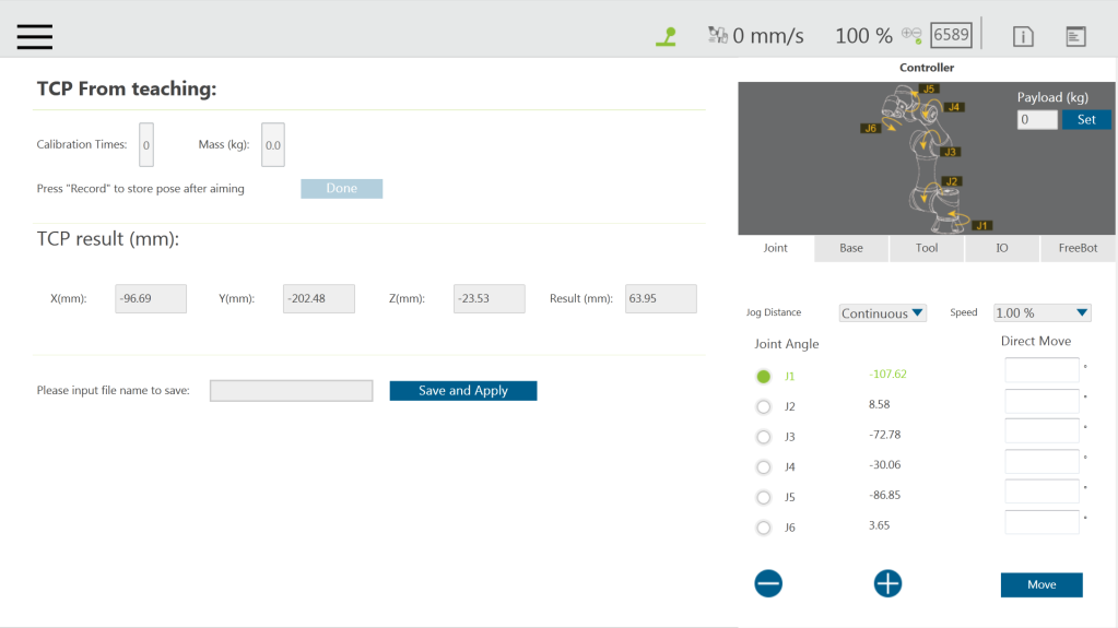
Step #4: Repeat this action until completed and the TCP numerical results and error values are displayed. After confirming that there is no mistake, input the tool name to save the file, and set it as the current tool for the robot.
Step #5: After teaching is completed, the positioning result will be displayed.
NOTE: It is recommended to calibrate this value equal or less than 0.3 to ensure accuracy.
NOTE: When using the Calibration Pin Set to teach TCP, the controller can be used to fine-tune the moving robot. Between each teaching point, it is still necessary to ensure that 1 to 6 joints are rotated.
Step #6: The calibration result can be saved for future use.