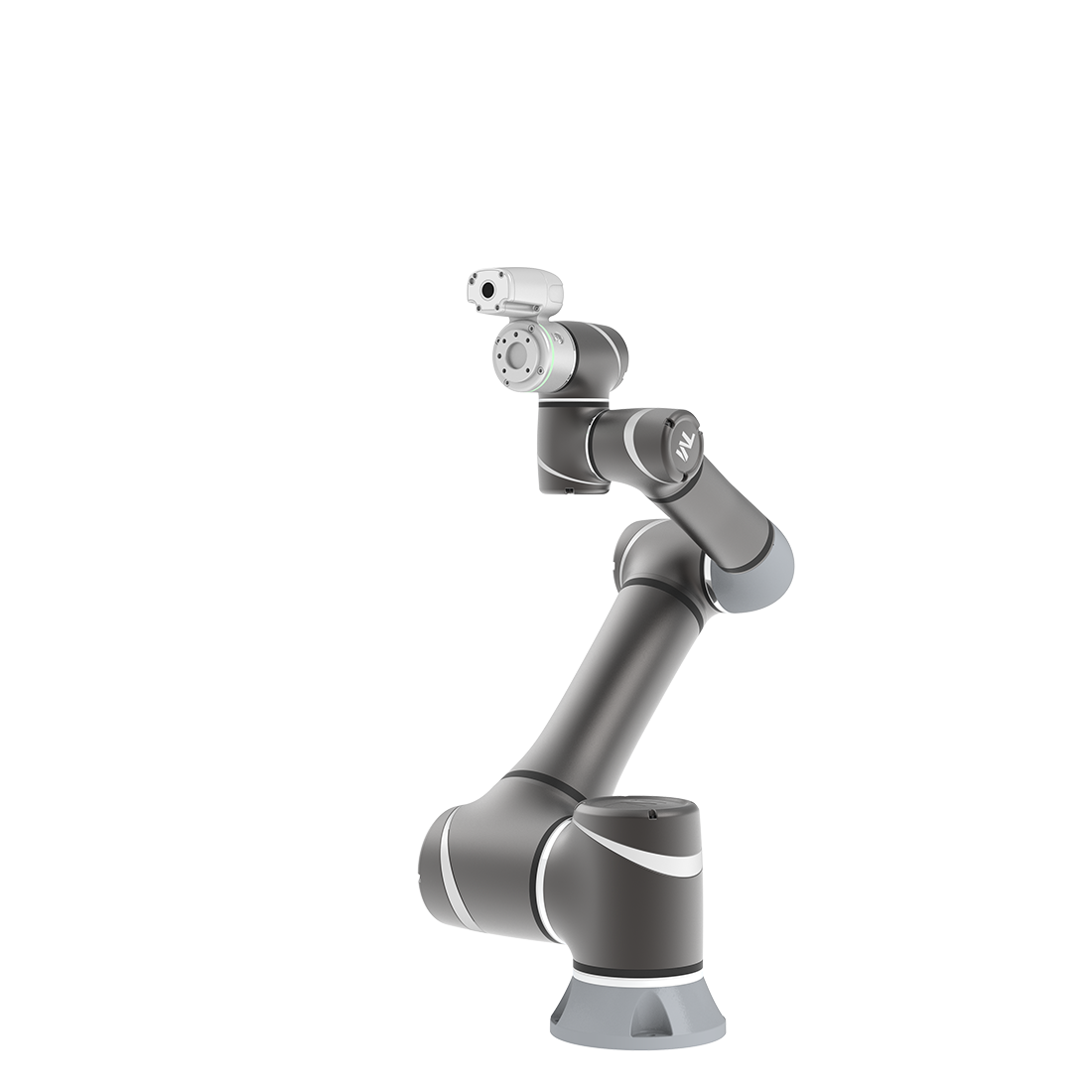
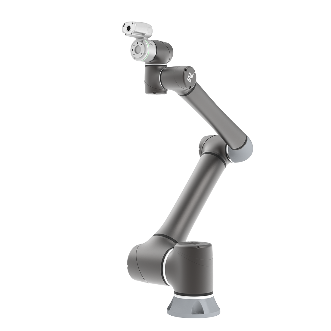
| Note:
1. Stop categories in accordance with IEC 60204-1.
2. The structure category according to ISO 13849-1:2015.
3. PL (Performance Level) in accordance with ISO 13849-1:2015.
Improvement & Scenario
- All Safety Functions are PL=d, Cat.3
| All 31 safety functions in TRSS5.0 (TECHMAN ROBOT Safety System 5.0) are complied with ISO 13849-1:2015 safety design and certificated with PL=d Cat.3 structure by TÜV NORD. These safety functions’ design meets the requirements in ISO 10218-1:2011 and also the ISO/DIS 10218-1:2023. |
 |
- Comply with the latest ISO/DIS 10218-1:2020 for future market
Although the ISO/DIS 10218-1:2020 is yet published, the TRSS5.0 is designed according to this version. In order to meet the requirements and the future market trend, TRSS5.0 has added certain safety designs:
- SF2- Encoder Standstill Output
ISO/DIS 10218-1:2020: The safety function shall provide a safety function output when the robot is in a monitored standstill condition.
SF2 Encoder Standstill Output comes with a safety output function to monitor the movement of each robot actuator through the joint encoder after triggered Category 2 Stop within a fixed time. If the joint encoder movement exceeds the acceptable range, the robot will perform a Category 0 Stop.
- SF19- Robot Stick Enabling Switch
ISO/DIS 10218-1:2020: Each teach pendant that can initiate motion or cause movement(s) shall have an enabling device in accordance with 5.13.
| SF15 User Connected Enabling Switch Input and SF19 Robot Stick Enabling Switch are designed to permit manual control operation while the Enabling Switch is at ON Status under MANUAL MODE. SF22 Enabling Switch on end-module is designed to grant robot hand guide teaching while the Enabling Switch on end-module at ON Status under MANUAL MODE.
|
 |
- SF24- End-Point Reduced Speed Limit
ISO/DIS 10218-1:2020: With the reduced-speed safety function, the speed of the TCP and the endpoint(s) of each joint of the manipulator shall not exceed 250 mm/s including the effects of any auxiliary axis. It should be possible to select speeds lower than 250 mm/s as the maximum limit.
The robot shall have reduced-speed safety function to enable limiting the end-effector or workpiece speed(s) to 250 mm/s or less. This safety function shall be used with reduced-speed manual mode. Figure 2 shows the end-points of each joint of the manipulator.
(Figure 2 from ISO/DIS 10218-1:2020)

| SF24 provides a safety function to set the robot end-point reduced speed limit. When any robot end-point exceeds the set limit under T1 MODE, it will initiate a Category 2 Stop. |
 |
- Enabling Switch on End-module
| Because the Enabling Switch is mandatory in ISO/DIS 10218-1:2020 under MANUAL MODE, and it is not convenient and not ergonomic while one hand holding the Robot Stick Enabling Switch and another hand holding the FREE Button to drag the robot. |
 |
| So, there is a safety-rated Enabling Switch on End-module in S Series robot. SF22 Enabling Switch on end-module is designed to grant robot hand guide teaching while the Enabling Switch on end-module at ON Status under MANUAL MODE. It would be easier to drag the robot using two hands. |
- Safety-rated RESET Function
| A protective stop is designed to protect operator from been harmed. According to the ISO 10218-1:2011 and ISO/DIS 10218-1:2020, the reset of a protective stop can be automatically, or manual. But if the RESET function of a safety function is not safety-rated, it would put the operator in danger. The case can be like this, a protective stop function, e.g. safeguard function by light curtain, is set to Manual RESET. An operator walk through the light curtain and the robot system stops, but the non-safety-rated RESET function goes wrong and resumes the system. The robot system resumes motion and collides into the operator. |
 |
| In case to avoid the above scenario, the TRSS5.0 has designed with safety-rated RESET function so that the resume of any safety stop can be ensured. |
- Auto Mode-only Safeguard Function
| There are scenarios that the robot systems are already integrated with safeguard devices, e.g. laser scanner, and work normally. Maybe one day, it requires a re-teach of the programming point but it is hard to remove or suspend the laser scanner. So the robot can not be moved or have any motion while the safeguard devices triggered, users have to remove the safeguard devices first to re-teach the robot. |
(example picture from internet)

|
| In case to avoid the above scenario, the TRSS5.0 has designed with Auto Mode-only safeguard function. If configured, the safeguard function will be in-effective under MANUAL MODE. The users’ safety will still be ensured by the Enabling Switch. |
- Clear Definition of Local Control & Remote Control
The robot will totally under Local Control while user is controlling the robot using the Robot Stick, which ensures the robot will not allow motion by receiving peripheral commands. The safety can be totally ensured. The Local Control and Remote Control according to Robot Stick status and operation can be summarized as the table below:
|
Enable/Disable status of Robot Stick function |
Operation Using |
|
| Local Control |
Enable, ON |
• Robot Stick
• TM Teach Pendant |

|
| Remote Control |
Disable, OFF |
• External IO connection
• Fieldbus command |
|
- Safe Home Output Function
| When robot is integrated on top of the autonomous guided vehicle (AGV). The robot only allowed to move when AGV reaches the station, and only when robot finished its task on the station, the AGV can carry the robot to leave the station. |
 |
| In addition, the pose of robot when AGV leaves the station is important. If error occurs from mis-programming, intrinsic protective stop of the robot, failure of the non-safety rated part, and the mistake in the latching state kept by work finished command from the AGV, the AGV may carry the robot to leave, with a non-desired pose, and will cause risk when AGV is moving, e.g .if the robot’s pose is extended out side of the area of the AGV volume to the floor, the robot arm may swap and crush to human when AGV is moving.
So, TRSS5.0 has designed to provided a Safe Home Output function to benefit the system integration with AGV. User can set the Safe Home pose of robot according to users’ application scenario.
If safe home pose is exceeded, an output shall be issued. The application scenario can be:
1. User can connect robot Safe Home Output to automated guided vehicle’s (AGVs) emergency / protective stop function, if provided.
2. While robot is out of the Safe Home, the AGV shall not move. While the robot is at safe home pose, the AGV can move. |
|
|