TM Component Editor provides developers the capability to compile nodes into components, which can be easily reused by other projects. It greatly simplifies the flow structure of repeating or similar applications. In addition, based on the diversity of product features, developers can plan the possible moving path of the robot in advance with TM Component Editor or design with the positioning of TM Landmark to create a variety of components applicable to screw driving, welding, polishing, and grinding.
IMPORTANT: TM Component is not designed for confidential encapsulation. Do not use TM Component in confidential usage.
Start creating your first component #
A component can consist of a variety of features to make the flow structure simple as well as reusable in other projects. TM Component Editor provides developers with a complete mechanism to create components. Among the nodes, the Start node can configure the component’s basic parameters such as display icon, usage, global variables, and its instruments. Moreover, developers are able to provide users to modify the parameters on demand. To help users to understand the usage scenarios of the developer’s component quickly, TM Component Editor manages a naming rule.
TM Component Editor settings #
Start node #
Developers can click on the Start node for basic settings. In the basic settings, Provider is the name of the developer, Name, and Type stand for the name and the type of the node respectively, and Icon is the image to represent the component. In addition, TM Component Editor can pack available Global Variables and instruments together into the component, and show the results in the branches of the Gateway node.
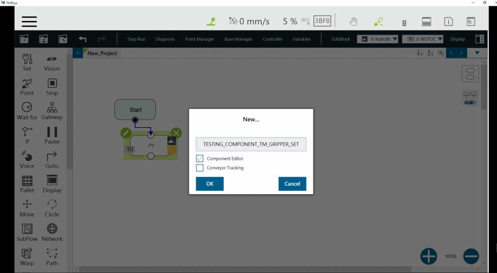
Step #1: Create a new project and tick ‘Component Editor’, project name naming rule is introduced below.
Component Naming: The naming rule of TM Component Editor goes by Application_Provider_Model_Version_Function.
Name Description & Examples
Application <—> GRIPPER
Provider <—> TechmanRobot
Model <—> Adaptive
Version <—> V001
Function <—> GRIPIMPORTANT: Do not use reserved words such as var in naming.
Step #2: The component is created successfully, fill the settings on the right Component Edit panel. Details are listed below.
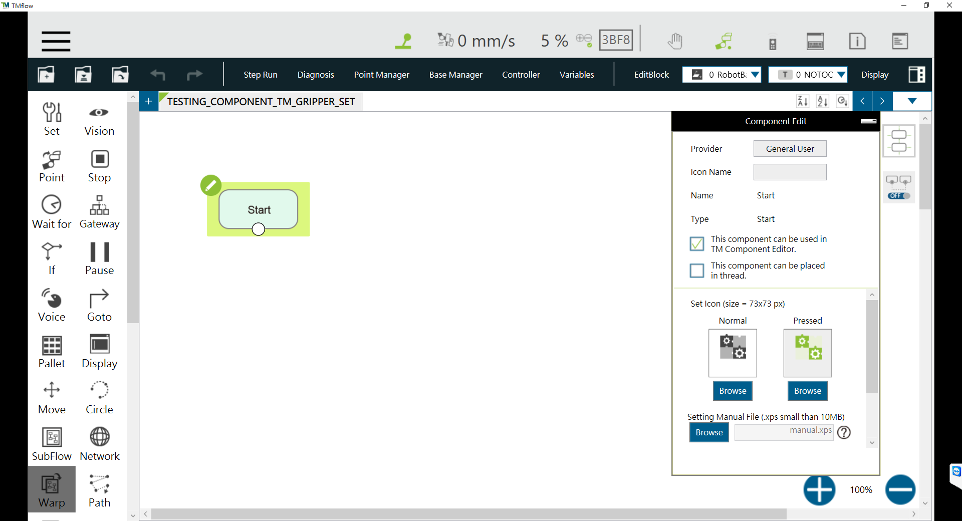
- Provider: Provider or company name that packs the component. When dragging a created component as a node in TMflow, the information of the developer will be displayed in the field.
- Icon Name: Users can use the desired name for the component listed in the node menu. Normally, a short form of the component name in order to not misleading users. The icon name is for use in the node menu only. Once dragged into the flow editing area, it displays the component name.
- Name: Name of the selected node. Developers may edit the name in the edit function of the node to optimize the visibility of the flow. This item can be used by developers to check the correctness of the current modifying node.
- Type: Type can be used by developers to check the correctness of the current modifying node.
- [Tick] This component can be used in TM Component Editor: This item sets if the component is available for use in TM Component Editor. Use component in TM Component Editor for the usage.
- [Tick] This component can be placed in a thread: This item sets if the component is available for use in a thread. To tick, the component must not involve motion nodes, or it will get a denial while saving the file.
- Icon: Developers can set up two different picture icons for the ‘normal’ and ‘clicked’ status of the component. Only image files in the USB drive labeled with TMROBOT can be imported.
IMPORTANT: The component’s icon supports PNG image files only, and the suggested maximum resolution is 73 x 73 pixels to avoid distortion or blur.
- Command List: This item sets the checked command sets embedded into the Component. When users import the component, the checked command list will be imported also.
- TCP List: This item sets the checked TCP list embedded into the Component. When users import the Component, the parameters will be imported also. The prefix of the TCP has to go with the first two names (Application_Provider_) of the project name in TM Component Editor; otherwise, they will not appear in TM Component Editor.
- Global Variable List: This item sets the Global Variables used by the developer embedded into the Component, so the variable conveyance in different Components is achievable. The first two names have to be identical to the names in the project; otherwise, they will not appear in TM Component Editor.
Global Variables Naming
The prefix of a Global Variable has to be the first two names (Application_Provider_) of the project name in TM Component Editor. Inappropriate naming of Global Variables may result in existing Global Variables being overwritten.
Select Exit From Gateway nodes #
This item sets the branches of the component. Developers have to select a Gateway node as the exit of the component and the possible results branch over the Gateway node exits according to the logic. Users can process the flow with the respective programs provided by the developers.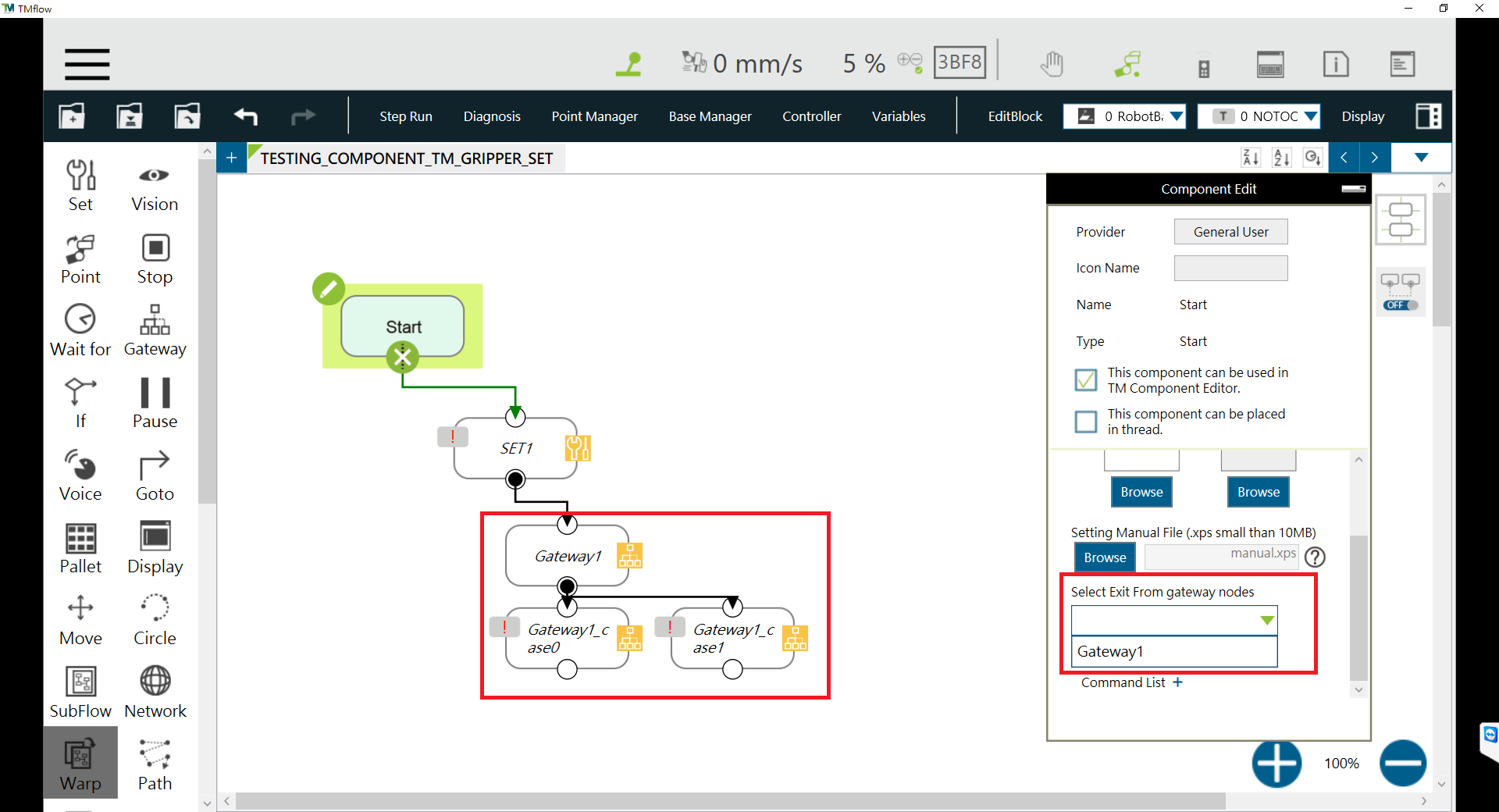
Node Setting #
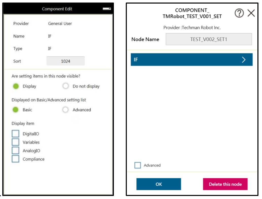
- Are setting items in this node visible: This item sets the node in TM Component Editor to be editable by users. When an IF node is set to Display and its flow is packed in a component, clicking edit in the component will present the node in the component as shown below.
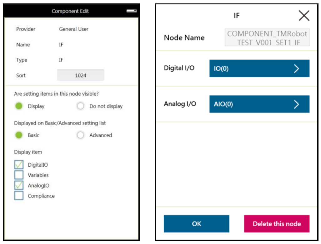
- Display Item: This item sets the items available for users to modify in the Component. For example, if the IF node is set to Display as shown below and Digital I/O and Analog I/O are both checked after the component is dragged into the project, users can select parameters of Digital I/O and Analog I/O to append or modify by checking the boxes in Display Item of the IF node in the Component.
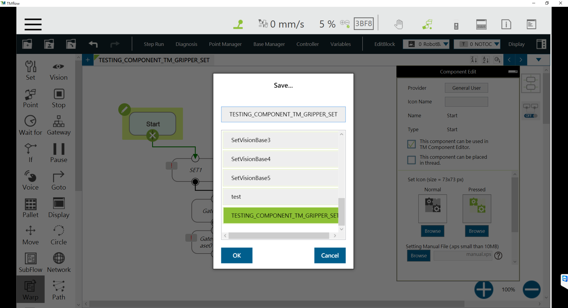
Save Component #
Click ‘Save…’ and click ‘OK’. The component can be imported/export to other devices.
Devices #
In TM Component Editor, you can edit the devices in advance, such as F/T Sensor devices, Modbus devices, Network devices, and embed the devices in the Component. The supported devices of TM Robot will be covered one by one below.
Modbus Devices #
Users can set the parameters of the Modbus TCP/RTU devices and have the devices embedded in the Component. By dragging the Component in TMflow to have a Modbus device added, users can configure the Modbus device in the list at the right of the screen.
Network Devices #
Users can add a new network device newly added by the Network node embedded to the Component. Dragging the Component in TMflow will add a Network device.
Force Sensing Devices #
Users can have the parameters of communication and physics in the force-sensing devices embedded in the Component. By dragging the component in TMflow, users can merely configure the serial port address to match the actually connected address for making use of the Component established with the device in the flow. If DeviceReadOnly is checked, users of the component will be limited to use the developer set devices.
Using Your Component #
Once you have completed the Component programming, you can export the Component to various projects or make the Component available to others. The following goes through how to open the Component and use it in the Project Page as well as how to make it available to others.
Import/Export Components #
Navigate to ![]() –> System –> Import/Export to export the component to the USB driver labeled with TMROBOT and import the component onto the users’ TM control box and make it available to users. Procedures can be found here.
–> System –> Import/Export to export the component to the USB driver labeled with TMROBOT and import the component onto the users’ TM control box and make it available to users. Procedures can be found here.
NOTE: Components created in newer versions of TMflow are not applicable to older versions of TMflow.
Open the component #
When selecting the Gateway node as the exit in TM Component Editor and clicking save, TMflow will create a component with the project. In the meantime, users can activate the created Component in the Component List by navigating to ![]() –> Setting –> Component, choose imported components and click ‘Save’.
–> Setting –> Component, choose imported components and click ‘Save’. 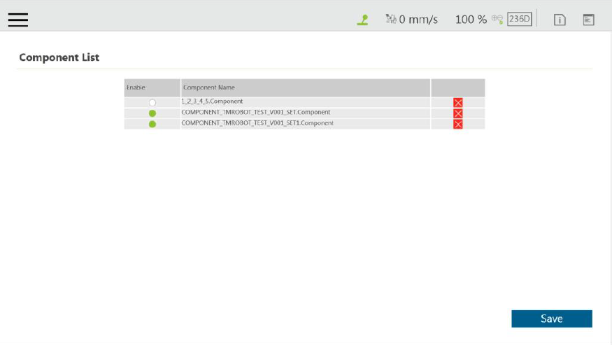
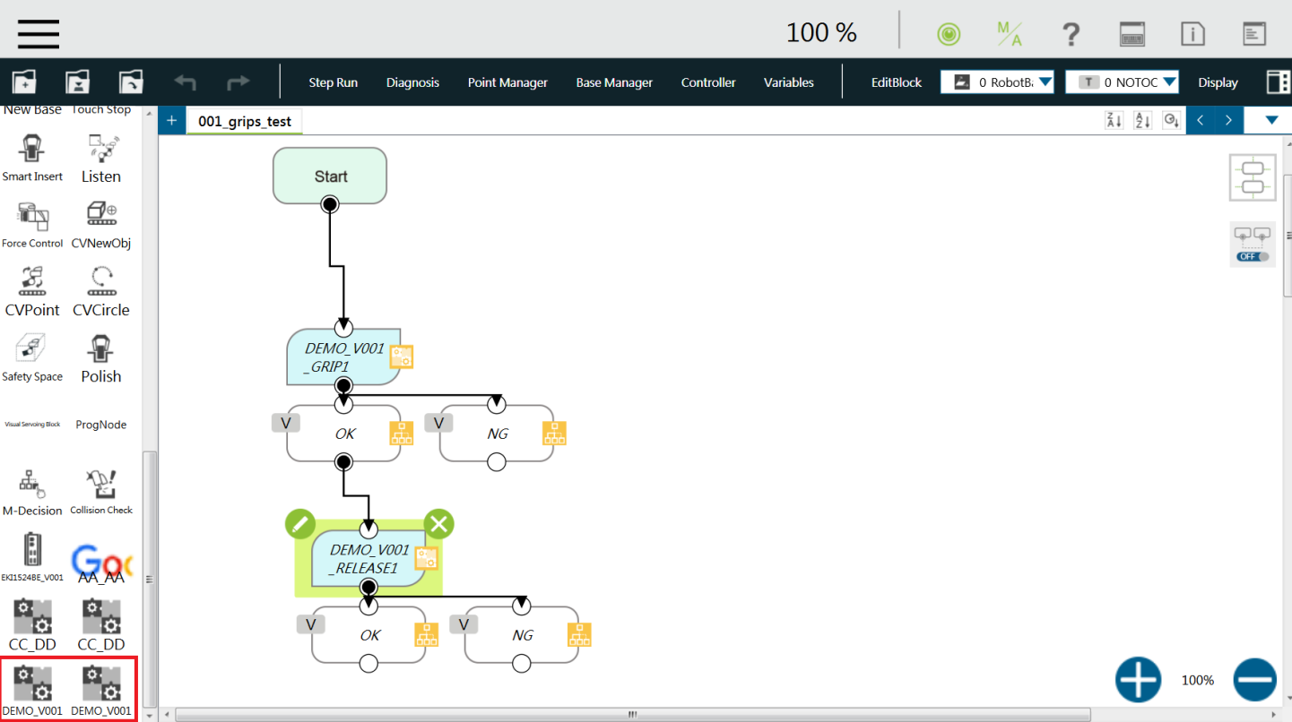
The Component should come out as a node on the left node panel. Below is an example of successful imported components.