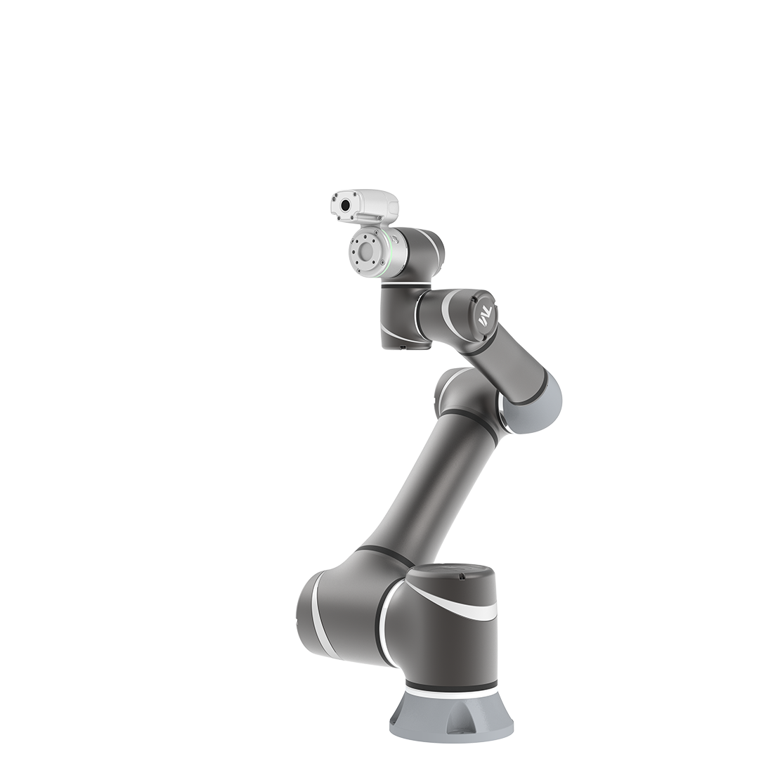
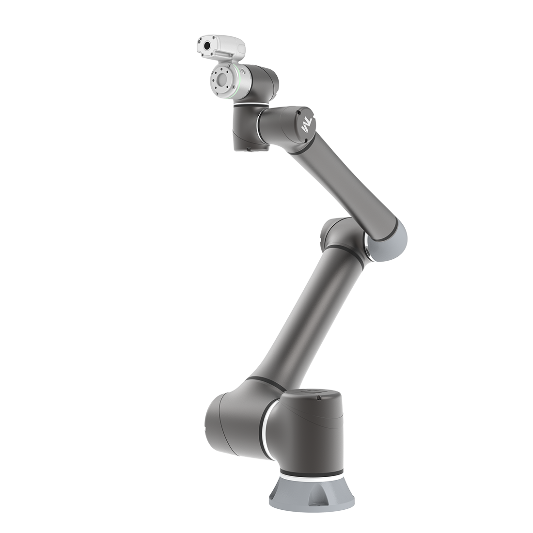
Skip to content

Eye-in-Hand Introduction

Overview #

The TM Robot’s built-in Vision Designer system integrates hands, eyes, and brains of conventional robots into one. This not only enables users to execute high-precision jobs but also provides flexibility for fast line changes. Regarding hardware operation, users can move the robot to right above the object and press the Vision button on the camera to generate a Vision node in TMflow for subsequent visual job programming. Refer to the relevant Hardware Installation Manual for the position of the buttons.

TMvision is designed for coordinate adjustment and vision job administration, and users can set parameters of visual features on lighting and imaging in the Vision node to enhance the speed and quality of identification. Refer to the following chapters for details and instructions.

Vision Base System Positioning Mode #

TM Robot comes with a 2D camera as the built-in vision system that supports the positioning model on the object-oriented base or the robot alignment-oriented base. For the object-oriented base positioning model, users must create a workspace and make sure the workspace is parallel to the object. Failure to do so may result in distorted imaging and visual identification job failures. TMvision offers four positioning methods: TM Landmark, fixed-point, visual servoing, and object-based calibration as described below.

TM Landmark #

TM Landmark provides a fast, simple, and flexible base system positioning method as a reference to the environment. Capturing TM Landmark with TM Robot will generate the position information of six degrees of freedom (including X, Y, Z, RX, RY, RZ) once to build a base system accordingly for users to record the following points and motions.

When the robot is repurposed or relocated when the relative position of the robot and landmark changed, it’s simple – use the robot to take a photo of the TM landmark again, to regain 6 DoFs of the new location and renew the landmark base system. The recorded points and motions on the Landmark base system will be converted to the base system automatically to make the robot move to the same TM Landmark is a 0.2 cm thick and 5×5 cm square plastic plate as shown in the figure below.

By capturing and recognizing TM Landmark’s black and white borders and central graphic features through TM Robot’s EIH camera, the robot can create the base system in the center of the TM Landmark’s black and white border.

Note that the accuracy of landmark positioning is not sufficient for identification and alignment purpose.

In principle, TM Landmark is not designed for users to have the robot directly go to individual points or execute motions after creating a base system. Instead, it is an alignment tool to lead the robot toward a valid visual point. Users should use the TM Robot visual positioning function to identify and locate the object in the last step to get the best results.

Fixed Positioning #

The fixed positioning function is designed with a pre-set object placement area and pre-set height for vision jobs. Users can create a workspace with the TM calibration plate. When using the TM calibration plate for fixed-point alignment, the relative height of the camera and the work plane are also defined. When using fixed-point alignment to establish a workspace, users must ensure that the absolute height of the camera and object is equal to the workspace created by the TM calibration plate.

Servoing #

The servoing function is for users to define the object features. In each servoing process, TMvision automatically sets the robot position based on the defined object to return the relative position of the camera and object.

Object-based Calibration #

The principle of object-based calibration is basically teaching as servoing and ending as fixed-point positioning. First, run the tilt correction with the calibration plate to define the visual servoing workspace with the actual workpiece and convert it to the fixed point positioning with calculations. Since the servo calibration is used only when defining the workspace for the first time, the robot will place the workpiece at the four corners of the camera’s field of view to create the workspace with four movements and make the fixed-point positioning calculation with the workspace accordingly. This takes advantage of the fixed positioning’s speed for positioning and the servoing without the calibration plate. For the object calibration, the features of the object should not be too big to fit in the field of view during the servo calibration.

Powered by BetterDocs