Examples are valid for
TMflow Software version: 1.76 or above
TM Robot Hardware version: All versions
Other specific requirements: No.
Note that older or newer software versions may have different results.
Goal #
Most common questions are:
- How to use BASE and TCP correctly?
- Could I record all robot points with default BASE (RobotBase) and default TCP (NOTOOL)?
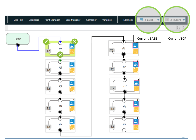
- Why there are different BASE/TCP on Points Node in my TMflow project?
- What are the meaning of CustomBase and VisionBase?
- How could I set multiple TCP if there are 2 grippers on my robot?
By reading this article, those questions should be answered.
Key Elements of a Robot Movement #
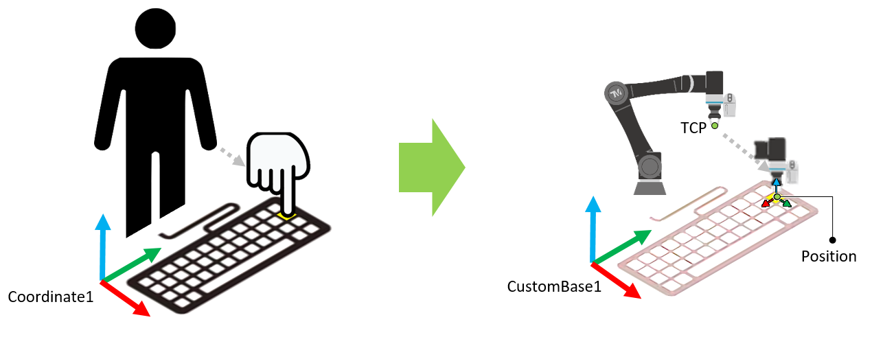
To begin with, we need to know the basic approach to control the movement:
Move something to somewhere.
For example:
Move [index finger] to [ENTER on the keyboard].
Translate it to robot command and it will be:
Move [TCP] to [ position referenced to CustomBase1]
Now we know the basic elements to complete a movement are:
Position
TCP
BASE(CustomBase, coordinate, origin)
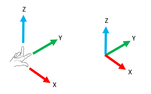
Notation of a Coordinate #
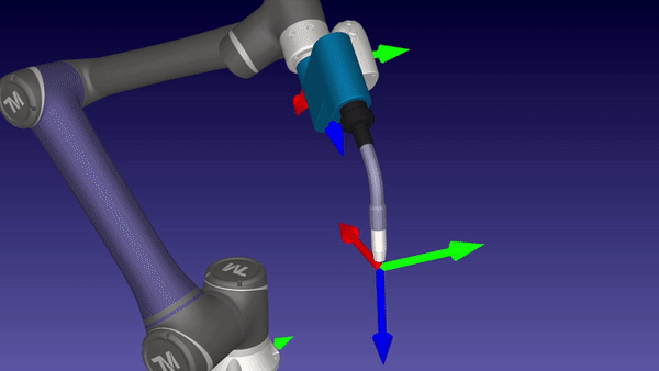
This is the notation of a coordinate. You can use the right-hand rule to know the relationship between X, Y and Z axes.
Where X axis is in RED, Y axis is GREEN and BLUE for Z axis.
Position #
Position describes how far and the orientation relativate to BASE.
It consists of [X, Y, Z, Rx, Ry, Rz]
Translation X, Y, Z #
[X, Y, Z] are the distance to BASE.X axis, BASE.Y axis and BASE.Z axis respectively.
The unit of [X, Y, Z] is length, normally is in mm, [100.5, -70, 33.1] for example.
There is an example of a position with same orientation to BASE(CustomBase1), [Rx, Ry, Rz] are [0,0,0] is this case: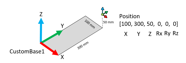
Orientation Rx, Ry, Rz #
The translation of X,Y,Z is easy to understand. But how about the orientation Rx,Ry,Rz ?
Just like X,Y,Z represents translation in 3-dimension world, Rx,Ry,Rz are for the orientation that X,Y,Z axis after Rotated.
There are lots of notations that could represnet orientation, TM robot uses EulerZYX noation for orientation, we will introduce EulerZYX at the end of this section.
The unit of Rx/Ry/Rz is ˚, range [-180.0~+180.0]. For example, [-45.9, 179.0, 30]
The direction of each axis could be found with right-hand rule too.
If the thumb represents the axis, then the four fingers are the direction of positive, or anti-clock-wise direction if you look from the top of thumb. 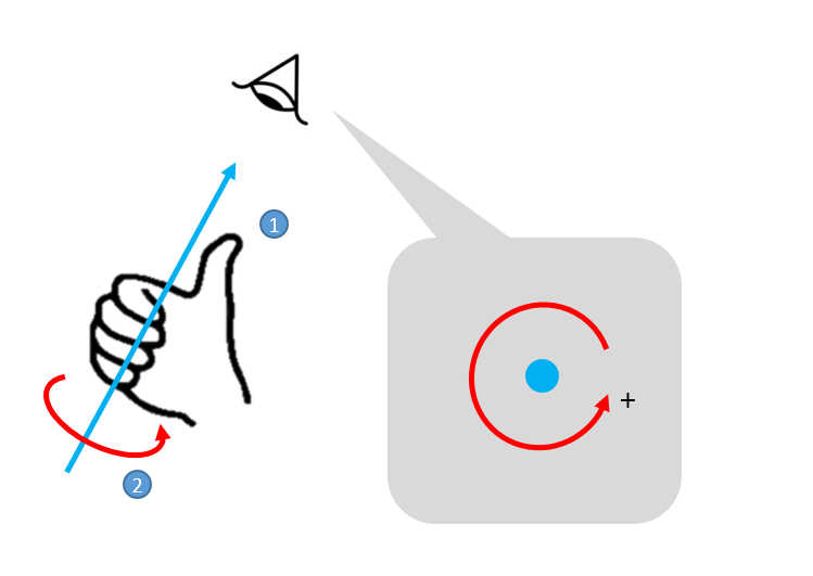
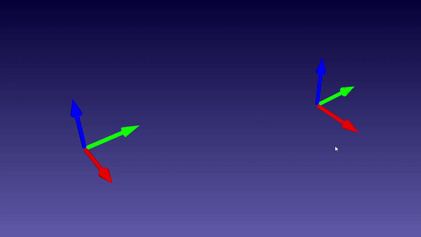
Example1 – Only Rz #
Continue with previous example, now we add Rz = +90˚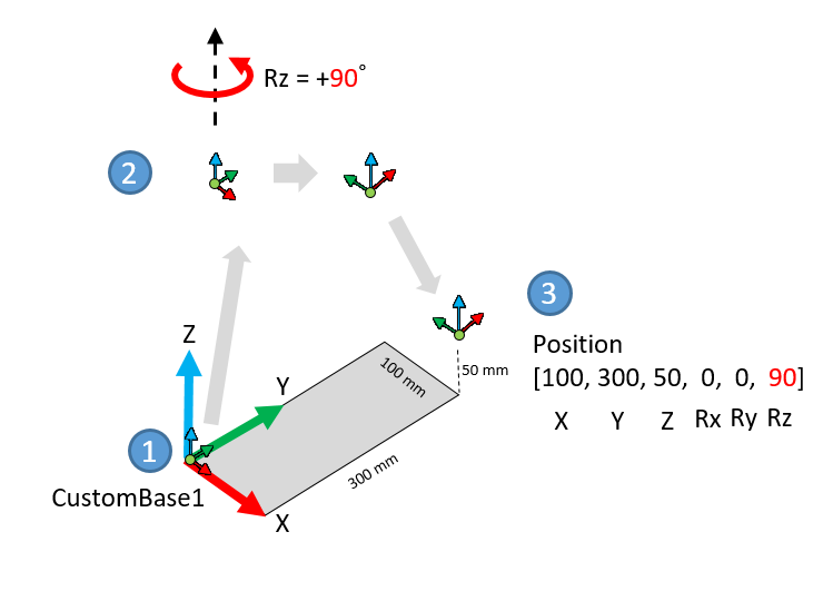
There is the animation of rotating in Z axis of +90˚
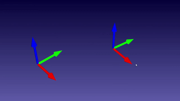
Example2 – Rz first, then Ry and then Rx (EulerZYX) #
Unlike X,Y,Z are independent to each other(and easier to understand), the relationship of Rx,Ry,Rz are much more complicated so we’re going to introduce EulerZYX.
EulerZYX Notation with Rx,Ry,Rz
Step1. With BASE coordinate, rotate Z axis in Rz˚
Step2. Then rotate Y axis in Ry˚
Step3. Then rotate X axis in Rx˚
Since it is in the order of Z axis rotation -> Y axis rotation -> X axis rotation, it’s named EulerZYX.
Here is the demonstation of the result after a coordinate roated with [Rx, Ry, Rz] = [30, -45, 90], easier to understand.
Note that anti-clock-wise is for positive direction.
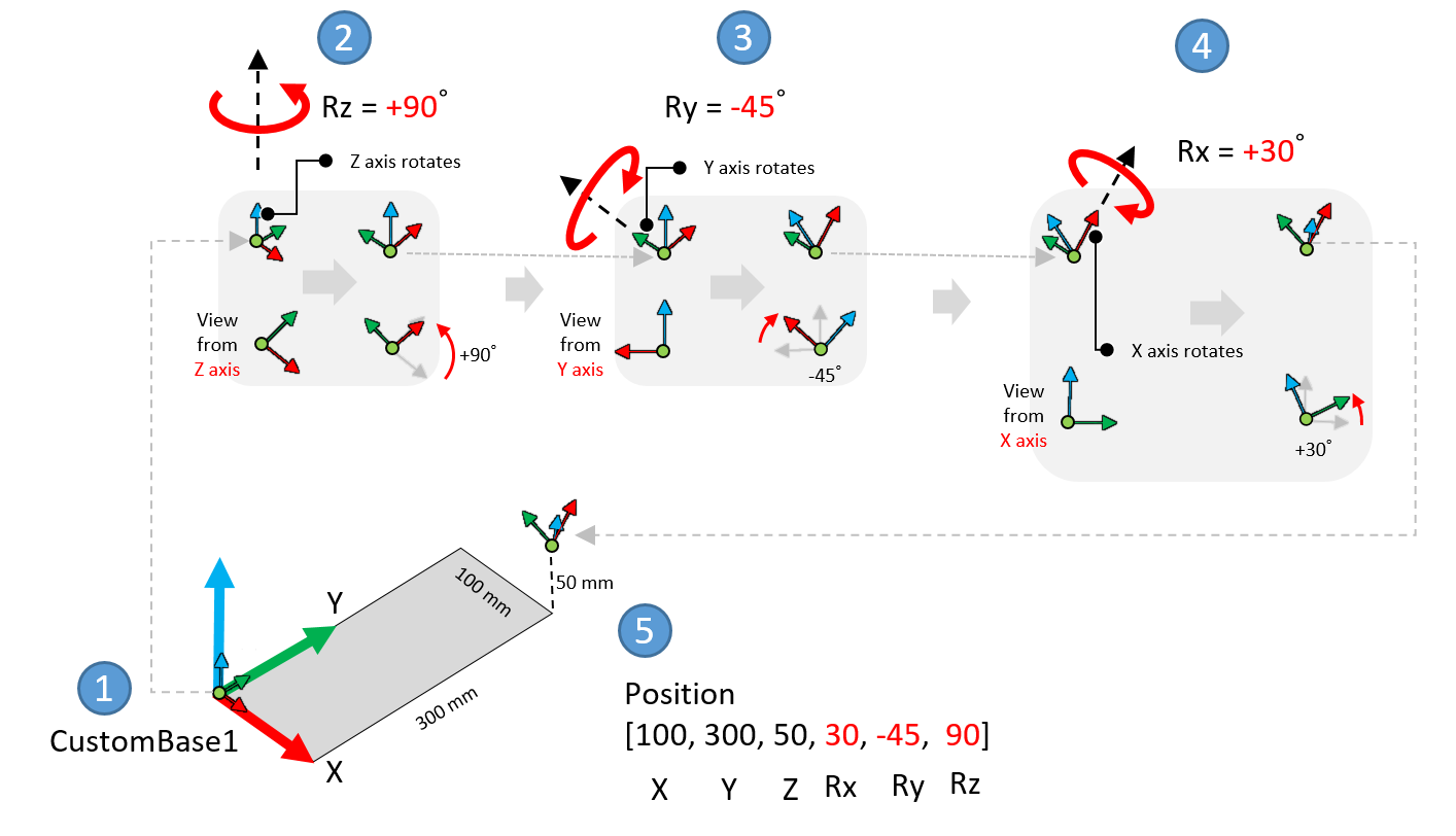
Note
(1) There are 12 combinations of Euler Angle representative, for example EulerXYX, Euler ZXZ…, EulerZYX is one of them and it’s most common in industrial robot system.
(2) EulerZYX mean rotate Z axis first, then Y axis and X axis respectively.
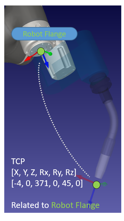
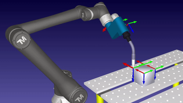
TCP – Tool Center Point #
TCP, as known as Tool Center Point, is the position value related to the robot flange.
Only ONE TCP works at the same time (currect TCP). It is NOTOOL(Tool0) by default.
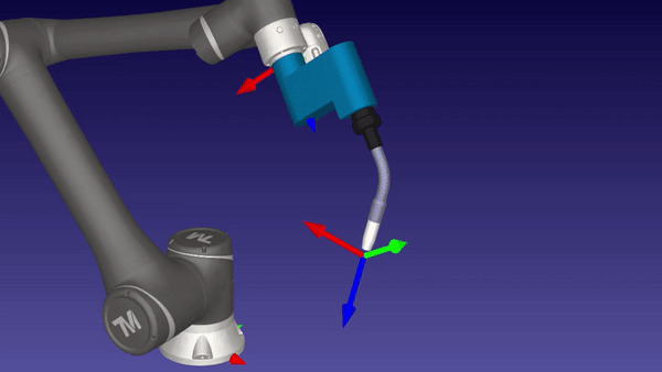
This is an example of a TCP on a welding torch:
Remember the first example : Move the finger to the ENTER on the keyboard? We will use the word tip(finger) to imply TCP in following section for better understanding.
Why TCP? #
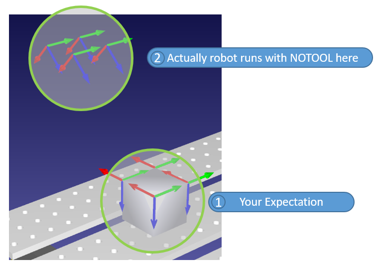
TCP means the correct tip that you’re using right now. To explain, let’s start with a scenario.
Move the robot to position-p1, related to BASE RobotBase. One with default TCP(NOTOOL), another one with a welding torch TCP(MyTCP1)
Both of them are physically same position in real world, but with different tips:
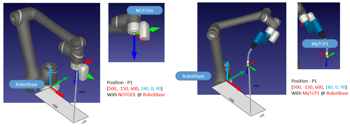
Here comes the advantages of using correct TCP.
Advantage1 – Jog the Robot with Correct Tool Tip. #
When you are teaching a point, it’s much more easier to jog if the robot know where the tip is. And you can rotate the tool at the specific point you want. That’s why we need TCP.
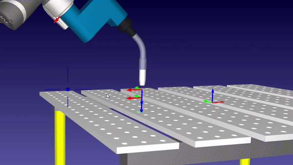
Advantage2 – Keep the Path wihle Modifying TCP Length #
Take welding application for example. If the path is taught with correct TCP, then you can adjust the value of TCP and the robot will try to keep the tip on the same path with different TCP offset. That will save plenty of time when you have lots of points to modify.
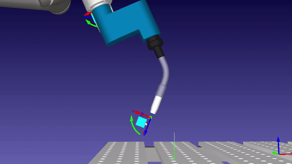
Advantage3 – Move the Robot along TCP Direction #
Correct TCP also tells the right coordinate to the robot, so you can leverage TMflow function such as MOVE NODE to move the robot along current TCP direction. It is useful in applications such as parts inserting .

How to Set TCP? #
There are two ways to enter the TCP value.
Go to TMflow > Menu > Setting > TCP Settings
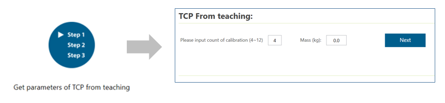
Method1 – Teaching
Install a sharp tip or needle on the TCP you want. Prepare another stationary tip on the table.
Teach the TCP with multiple points. Please refer to TMflow manual or search UNDERSTANDING THE VISION BASE AND TCP in technical document for more information. But you can not teach the Rx, Ry, Rz for TCP with this method.
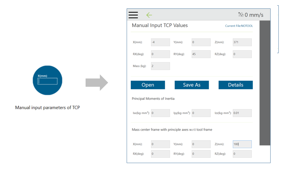
Method2 – Direct Inpiut
Get the position value of the TCP in CAD software, you will need at least [X, Y, Z, Rx, Ry, Rz]
Note that the mass and the center of mass are necessary or the robot might detect collision during running project with wrong mass data.
Once the TCP is set properly, you can check if the tip(TCP) is stationary in space when you jog the robot with rotational movement.
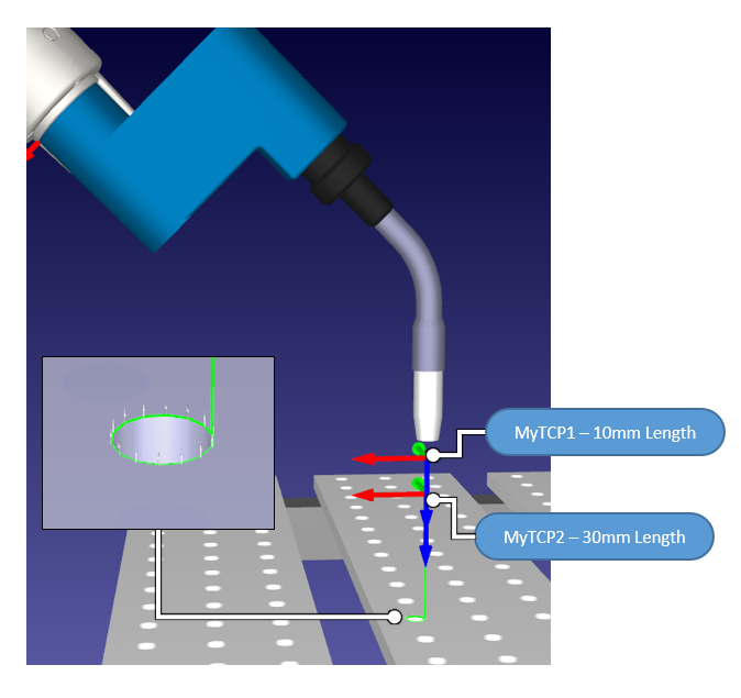
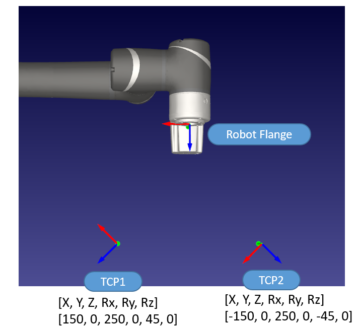
Exercise – Two TCP #
Here is the excercise for two TCP setting. This configuration of tool usually used in machine tending.
Please calculate TCP1 and TCP2 in [X,Y,Z,Rx,Ry,Rz] with desired direction as below.
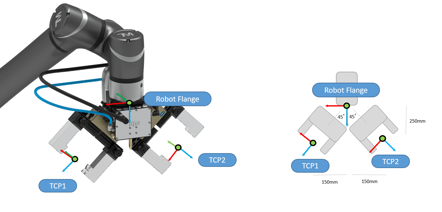
Here is the answer:
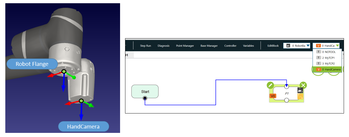
TCP – HandCamera #
With robot that equipped with camera on hand(or Eye-in-Hand camera, EIH camera) after vision calibration, there will be a TCP named HandCamera. That is the TCP mounted at the center of camera. You can use it as a normal TCP in vision application.
BASE- The Origin #
BASE is the origin or the coordinate, which is the reference that Position[X,Y,Z,Rx,Ry,Rz] refers to.
BASE is the collection of CustomBase, VisionBase, RobotBase.
Only ONE BASE works at the same time (currect BASE). It is RobotBase by default.
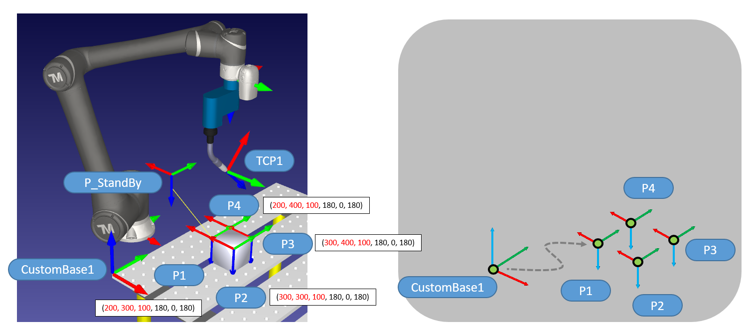
Let’s consider the simple scenario, run the robot with points:
P_StandBy -> P1 –> P2 -> P3 -> P4 -> P1 -> P_StandBy, with a BASE named CustomBase1:
Each point are refer to CustomBase1. Take P3 for example, the position of P3 = [X,Y,Z,Rx,Ry,Rz] = [300, 400, 100, 180, 0, 180] related to CustomBase1:
Note that [Rx,Ry,Rz] is [180,0,180] since it’s rotated with Rx and Rz compared to CustomBase1:
Why BASE? #
There are advantages of using correct BASE:
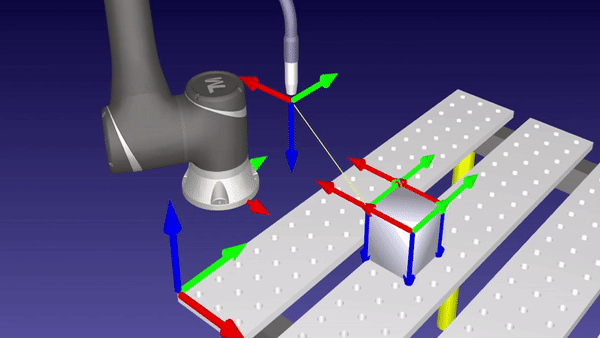
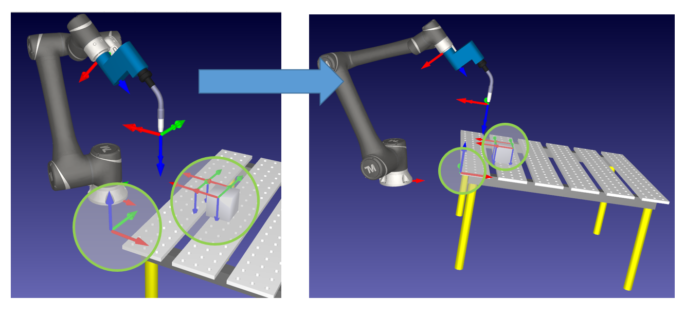
Advantage1 – Path Correction & TMLandmark #
When the table(where the BASE is attached to) moves, you can re-define the BASE so all the path should be correctd at the same time. It’s not easy and you will need to modify all the points if you don’t have correct BASE.
Even the table is tilted, the correct BASE will tell the robot where the correct path is:
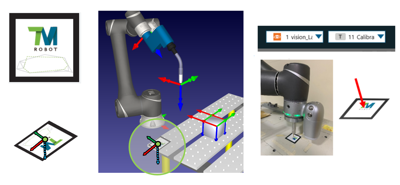
TM Landmark is a powerful gadget working with EIH camera. Create a VISIONJOB NODE in a TMflow program, then the robot will update the VisionBase everytime when it find a TM Landmark in sight. It WORKS even if it’s tilted since the robot could recognize it in 3D space.
Please refer to TMvision manual or search UNDERSTANDING THE VISION BASE AND TCP in technical document for more information.
Advantage2 – Point/Path Duplication #
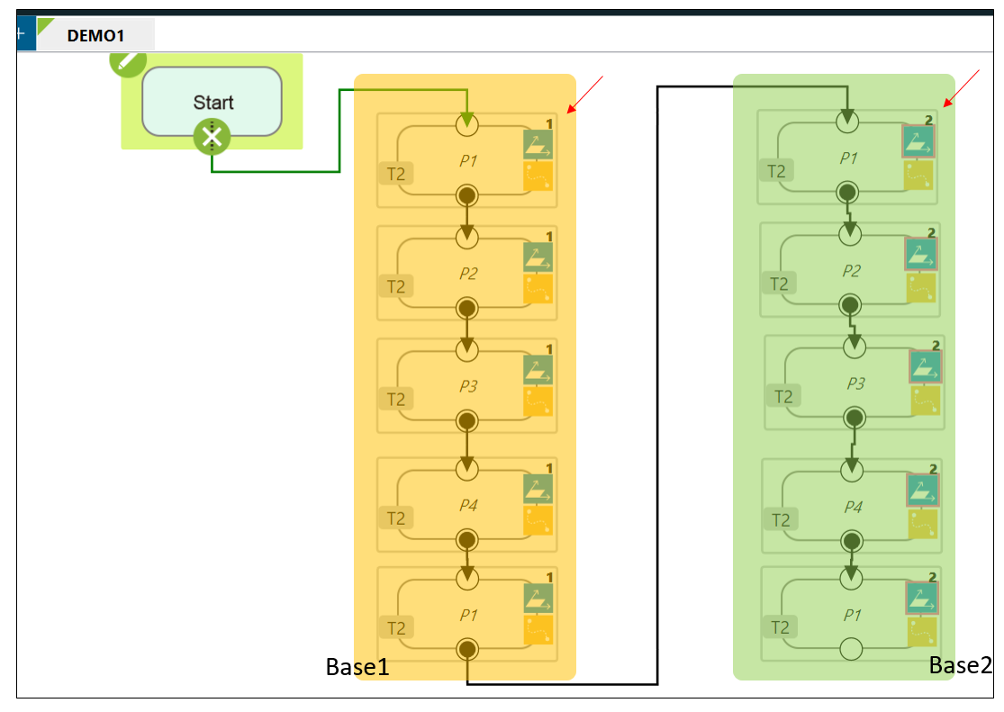
You can duplicate path from table1 to table2, table3…and so on.
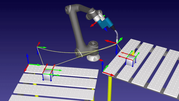
You can duplicate POINT NODE and assign them from BASE1to BASE2 and more.
By this method, you can duplicate many tasks with specific BASE without teaching points one by one. It will save plenty of time especially when there are lots of points to teach.
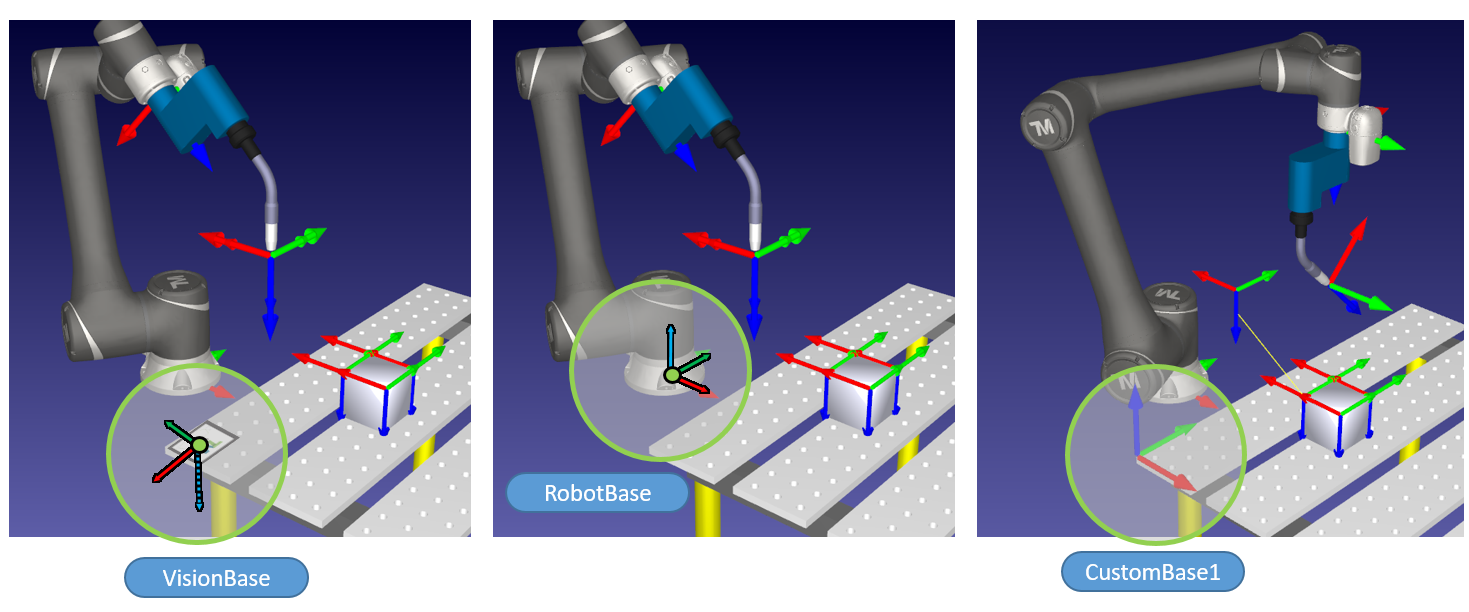
BASE – RobotBase, CustomBase, VisionBase #
BASE is the collection of CustomBase, VisionBase, RobotBase, here is the comparison.
CustomBase : The base that you can define, you can create it by yourself. Could be more than one.
RobotBase : Fixed at the buttom of robot, could not be modified. Only one.
VisionBase : Exists when a VisionJob is created. Could be more than one.
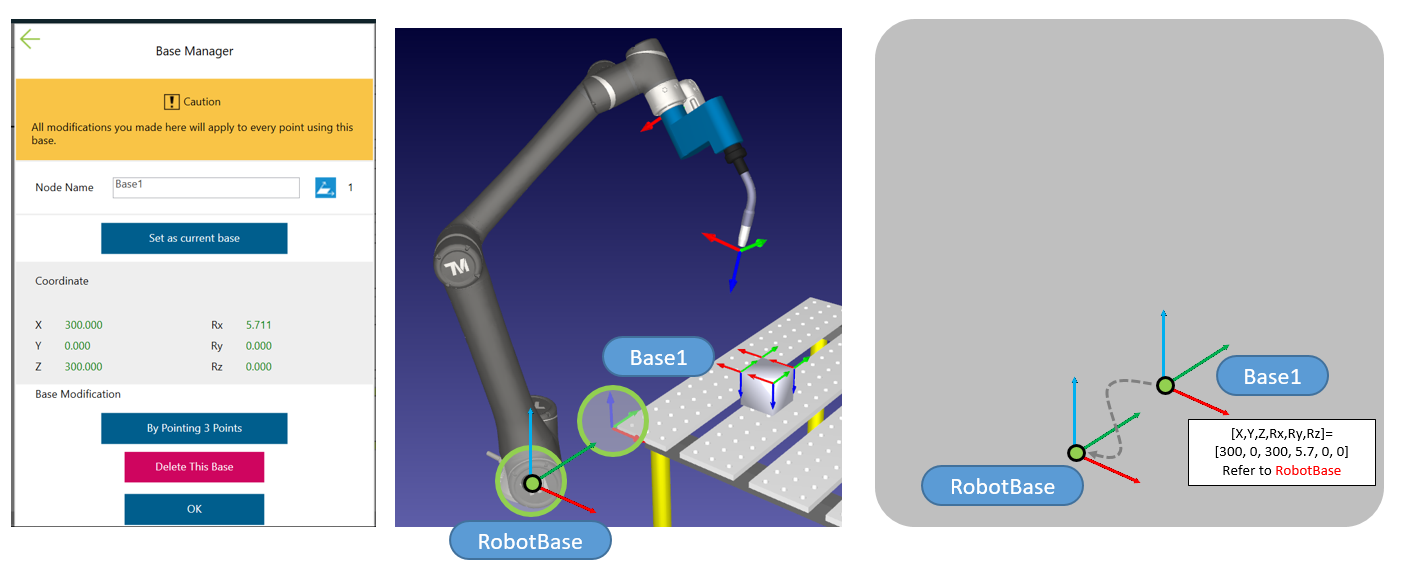
How to Define BASE? #
- Create a correct TCP first
- Go to TMflow > Menu > Project > Base Manager > By pointing 3 points to define a new BASE
Please refer to TMflow manual for more information.
Here is the example of defining a BASE Base1 with [X,Y,Z,Rx,Ry,Rz] = [300, 0, 300, 5.71, 0, 0], this position value refers to RobotBase.
Conclusion #
- Define and select correct TCP and BASE when you start a new TMflow Project
- Leverage the advantage of TM Landmark in your vision application
- Everytime when a point is created, robot will record the current position based on the current BASE and TCP
Q&A #
I had calibrated TCP and BASE already, but there is still little deviation when I duplicated a path from other robots? #
There are lots of calibrations that should be done on the TM robot(EIH calibration, DH calibration…etc). But even if every calibration is done correctly, there are still tiny deviations(could be several mm in some cases) comes from the sum of:
- TCP deviation
- DH deviation
- Camera deviation
- Mechnical tolerance
- …
With correct BASE and TCP, you can minimize the time to duplicate path to targeted robot. But in case you need very accurate position(i.e., less than 0.5mm), we suggest you to re-reach the point node directly.
Could I use robot without TCP and BASE? #
Sure. Actually you’re using TCP NOTOOL(at robot flange) and RobotBase(at the bottom of robot). Normally there are no difference if you just look the robot while running no matter with your TCP or NOTOOL. But in the future, if you want to extend the length of TCP, you have to re-teach all points.
Instead, if you used correct TCP at the beginning, you can modify the value of TCP and start to run your project, it will be easier for you if there are lots of points to re-teach.
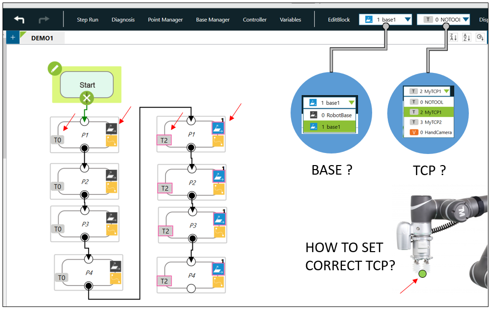
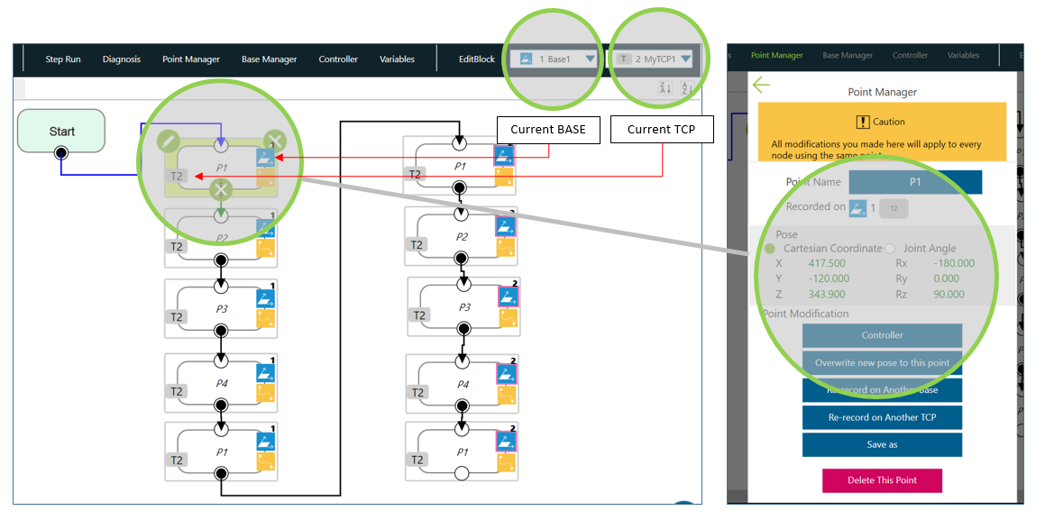
How Could I switch TCP and BASE? #
In manual mode, select BASE and TCP here and the robot will know which of them are using.
When you run a TMflow project, the robot will switch to specific BASE and TCP based on the setting in movement node such as POINT NODE and MOVE NODE.