Examples are valid for:
TMflow Software version: 2.20 or above.
TM Robot Hardware version: All
Other specific requirements: None
Note that older or newer software versions may have different results.
Modbus Communications Protocol #
You can use Modbus Master Command to read/write the parameter such as position, pose, etc. in a register and use the parameter to edit the project or monitor the robot.
TM robot provides TCP/RTU communications protocol. The user can adjust according to the actual status. (Refer to chapter 2)
TM robot can have both TCP and RTU status. The user can obtain an external device of Modbus or robot register data. Third parties can also use an external device such as IPC, PLC, etc. to be the
master to send the command to obtain relevant information.
Note: In this Instruction page, Client is called Master; Server is called Slave.
Remark: Modbus table can be downloaded in the bottom of the page.
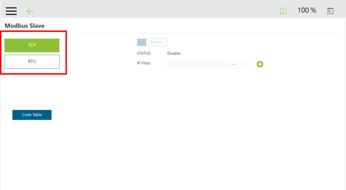
On the HMI (human-machine interface) setting page, click on Communication to enter the “Modbus Slave” page
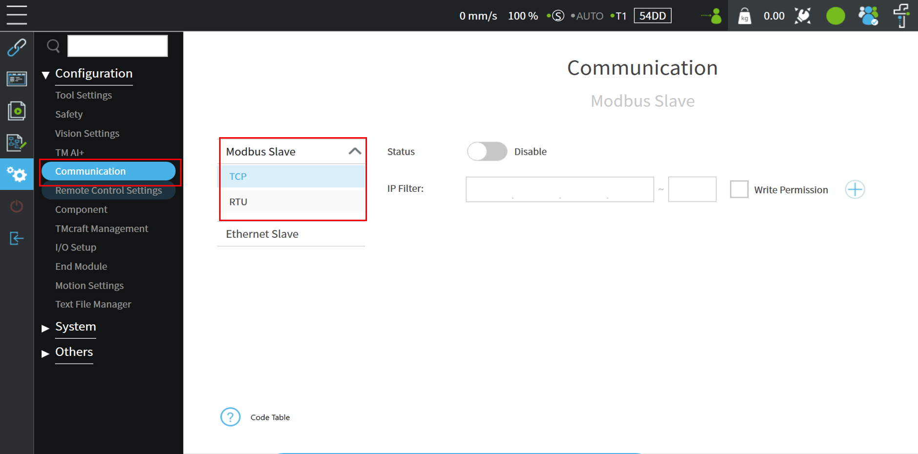
Modbus TCP Architecture #
Modbus TCP communicates via RJ-45. There is only one RJ-45 connector that can be utilized to communicate in the control box. The setting page can check the IP filter and Modbus status.
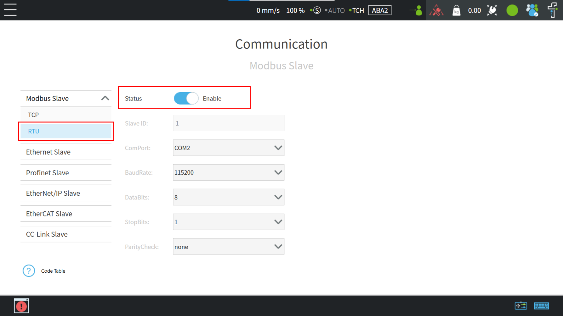
Modbus RTU Architecture #
in Modbus slave page, make sure the parameters of setting and external device are synchronized. if the setting is correct, the user can enable modbus RTU to communicate with the Modbus Slave or Modbus Master.
Modbus RTU communicates via serial port. The setting interface can check the status, baud rate, port number, slave id, etc.
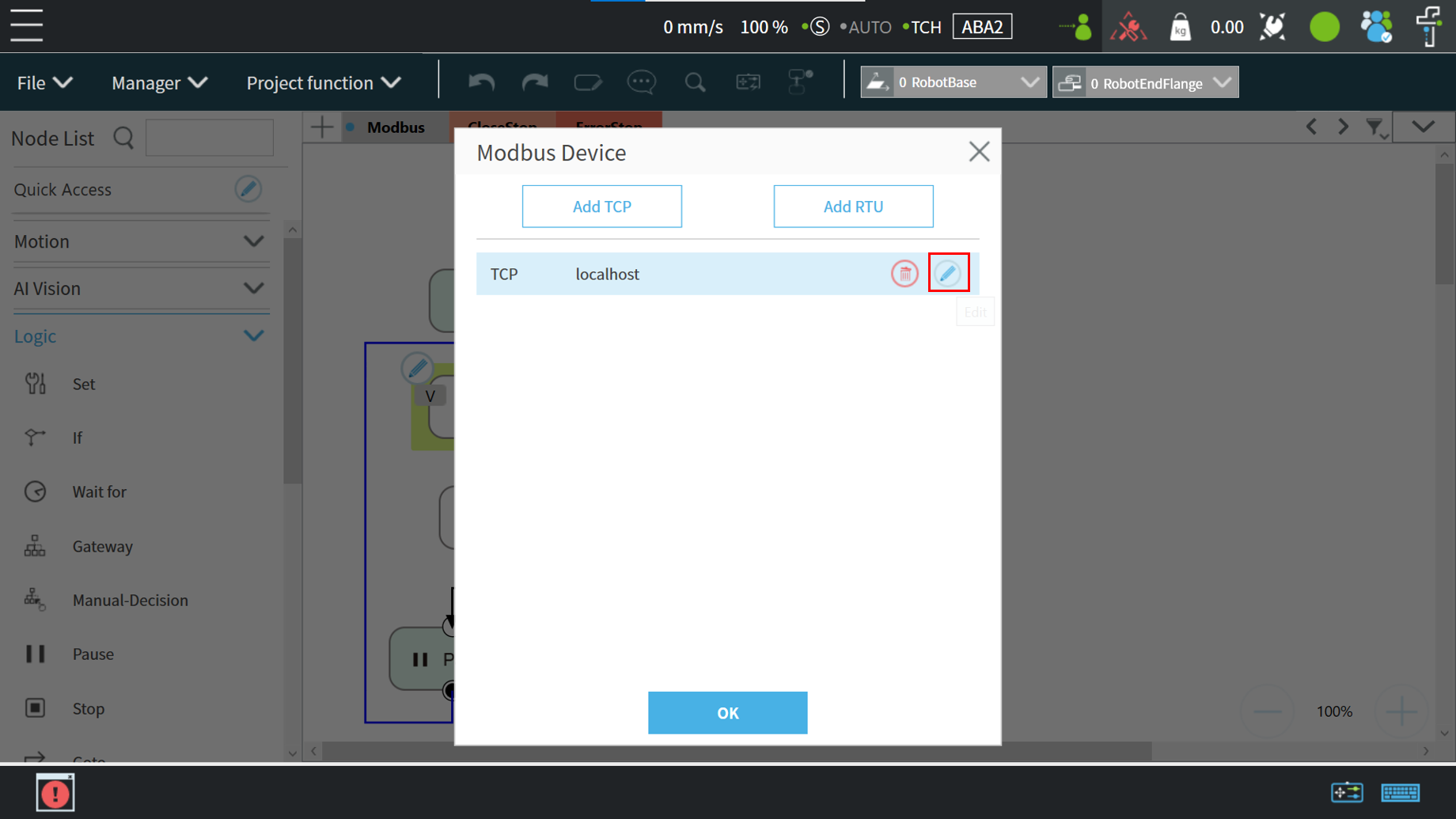
Add a TCP Device #
TCP Device Setting #
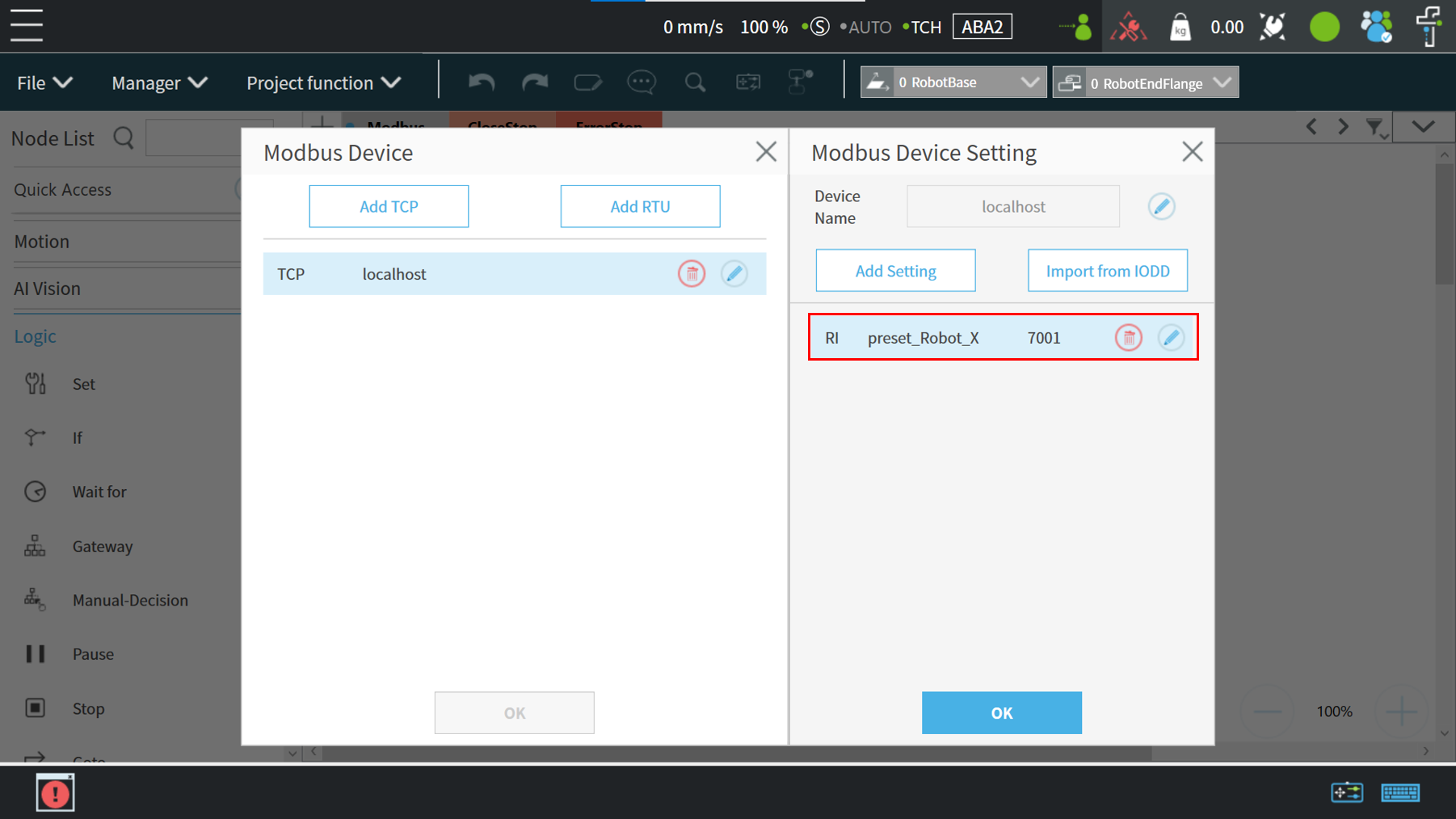
Click the “Project Function” button and select”Modbus Device”
Click Edit (pencil icon) next to the TCP localhost selection , select “Add Setting”
Set the parameters of the TCP device such as:
- Input a device name,
- Slave ID, modbus address, type.
Press the OK button to save the parameters.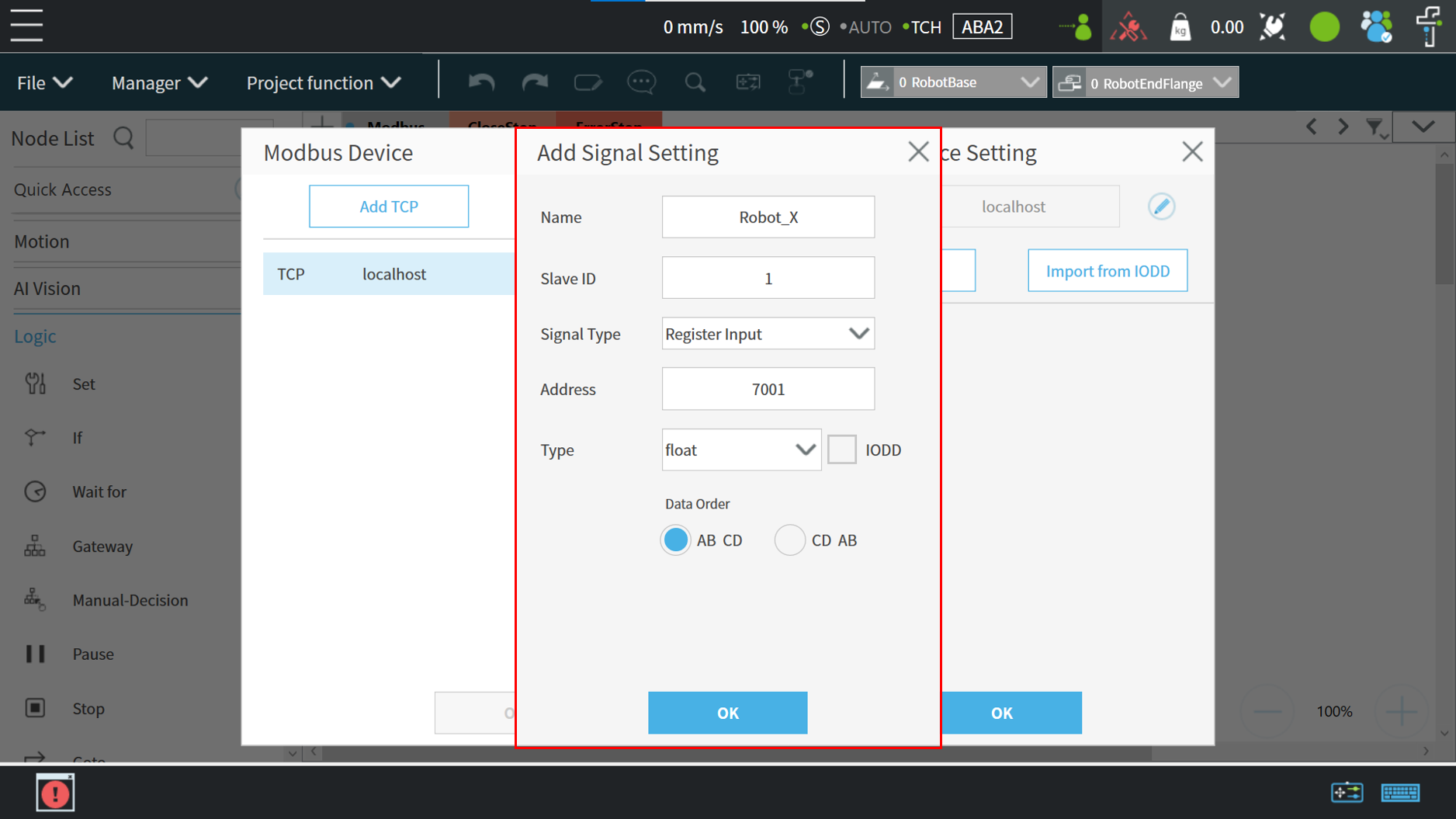
Simple Read Values Example by Modbus Register #
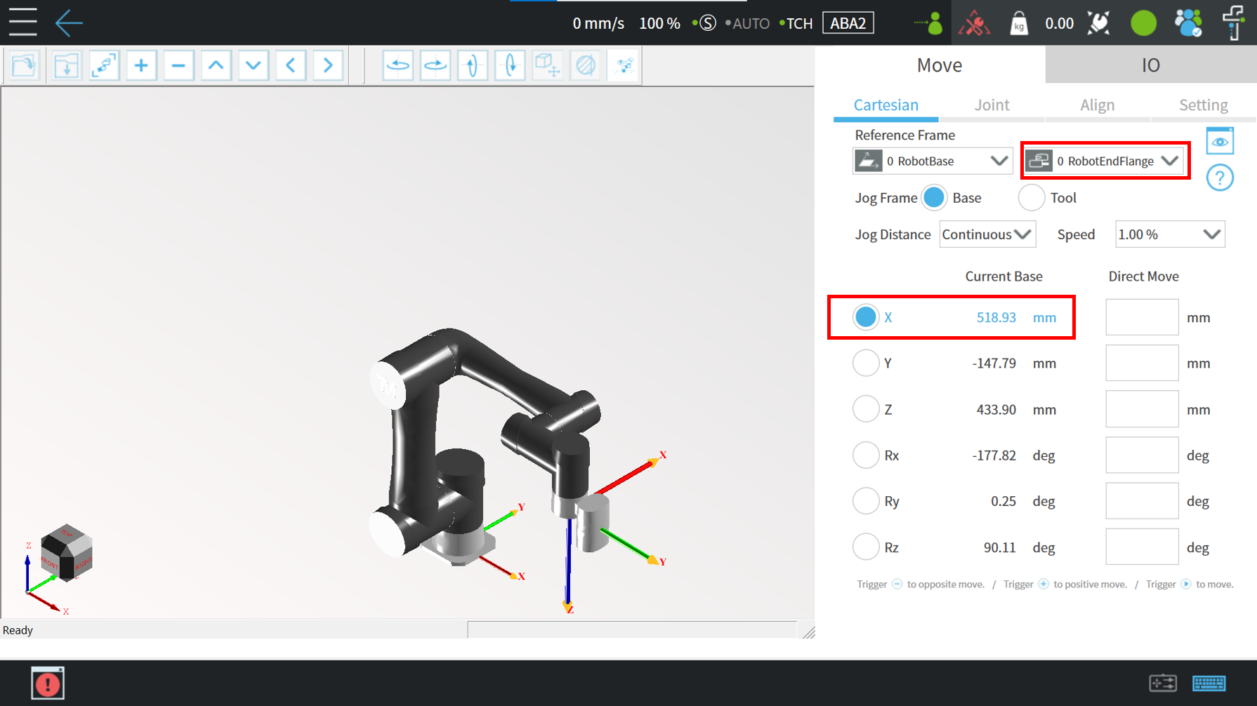
The following example will show how to access the X Coordinate of the TM robot when editing flow. Users must create a variable for storing the X coordinate value of the register.
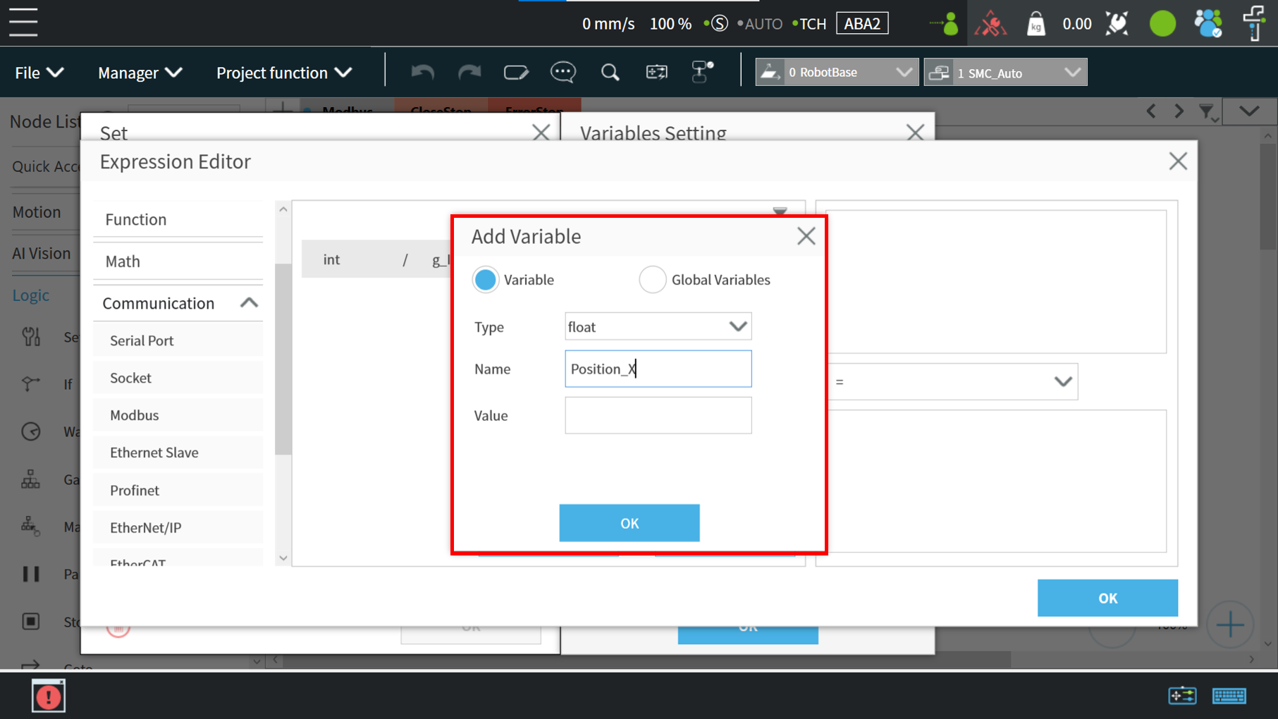
Create a ‘Set’ node and click on the pencil icon
First, user must create a variable for storing the X-coordinate value of the register. In this example, create a float variable type
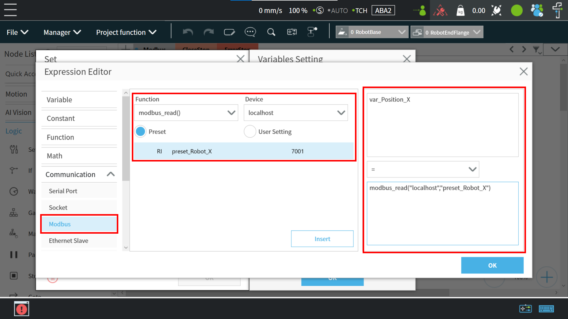
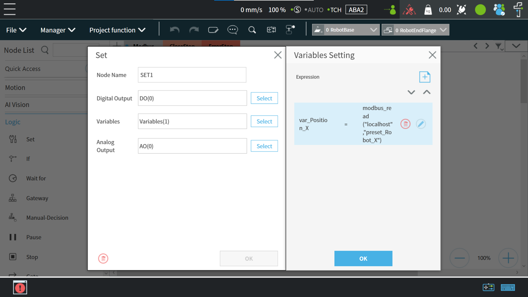
In order to make the variable “var_Position_X” automatically obtain the coordinate value of TM Robot in the X direction, configure the Modbus read function as follows :
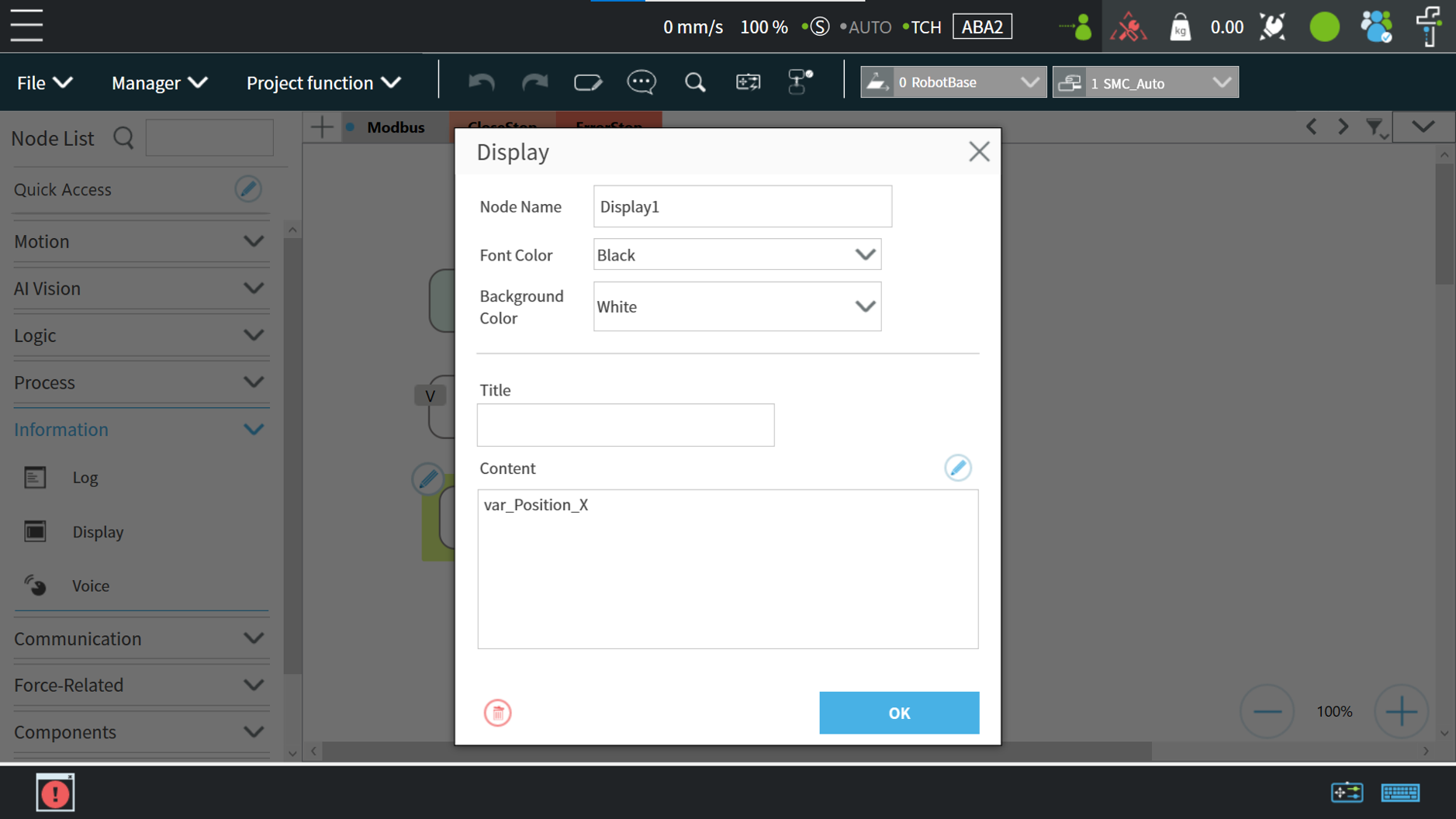
Add Display Node
Users can see the value through display node and verify whether the value from Modbus colide with the X coordinate of the TM Robot
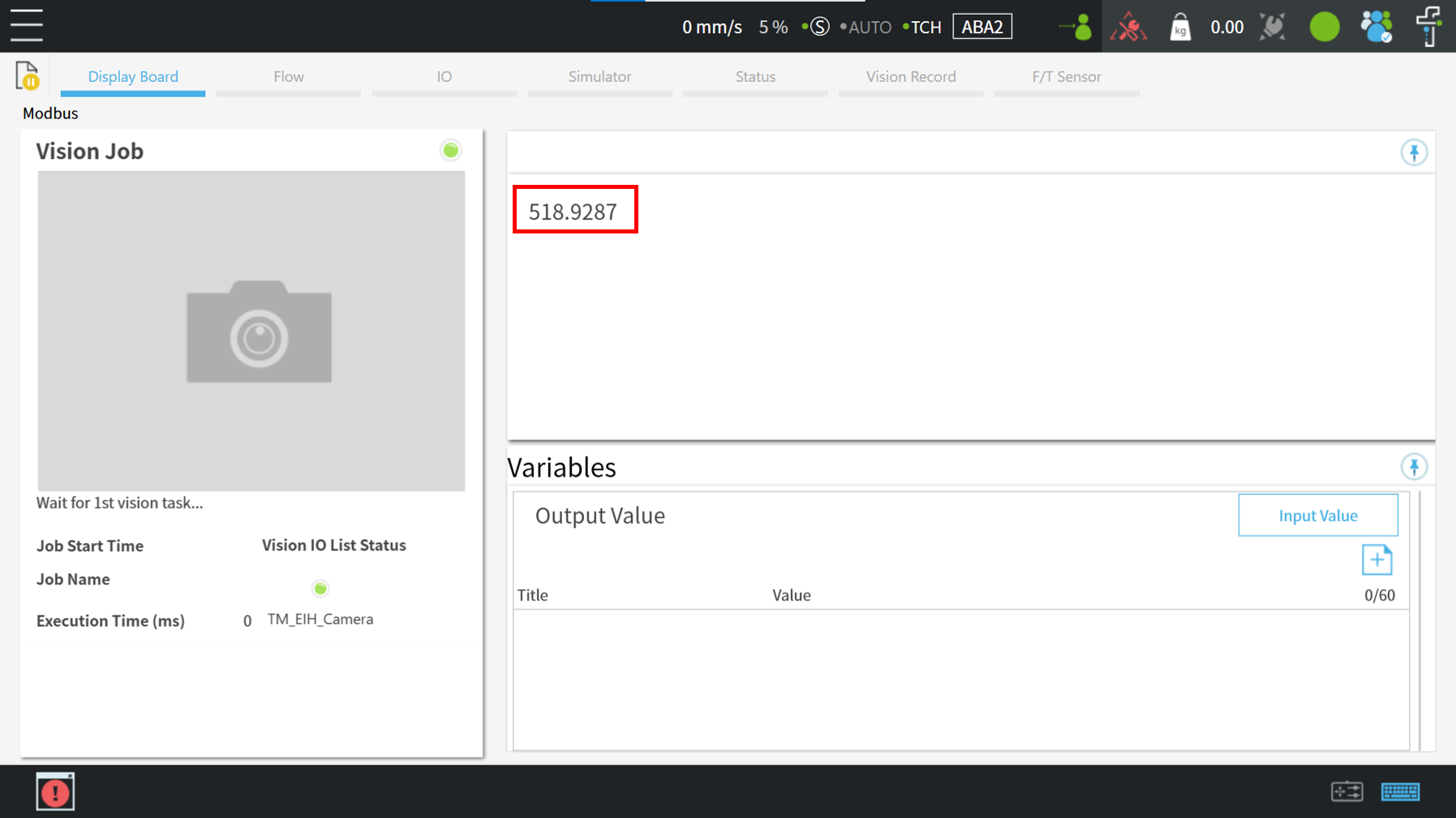
Play the project and see the result


