Examples are valid for :
TMflow Software version: 1.76.6300 or above.
TM Robot Hardware version:All versions.
Other specific requiremnets : None
Note that older or latest software versions may have different results.
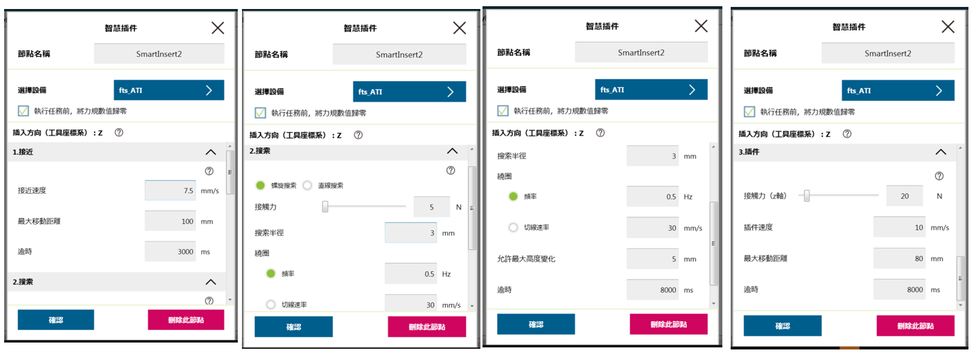
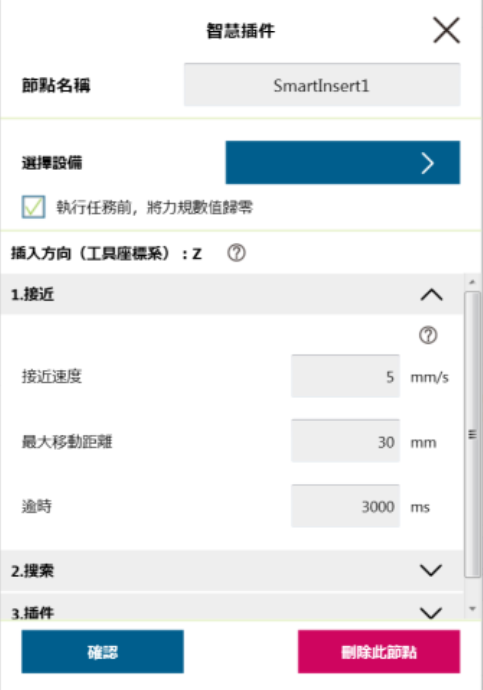
1.Approaching
- The maximum moving distance can be increased a little to compensate for the offset of the object along the Z-axis in the tool coordinates.
2.Searching
- Frequency,set to the lowest setting
- Search radius,set from the smallest, then gradually increase
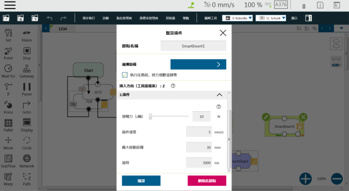
3.Inserting
- Contact force,increase from small to large
- Speed,increase from small to large
- Moving Distance,increase from small to large
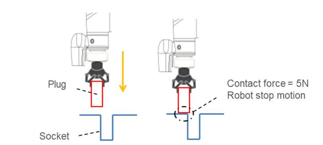
Before using the smart insert node,users should bring the part to be inserted as close as possible to the assembly process. In the approaching step, the robot will move forward along the z-axis of the tool coordinate system until the force sensor detects a resistance of 5 Newtons (N).
| Important:
Because the contact force needs to reach 5 Newtons for the approaching step to end, users need to ensure that both the insert and the receiving part can withstand at least 5 Newtons of force to avoid product damage. |
Approaching Parameters Setting #
The Smart Insert node provides 3 configuration parameters for the approaching phase :
- Approaching Speed : Range is from 0.5 to 10 mm/s.
- Moving Distance Limit : Range is from 1 to 100 mm.
- Time Out : Can be set between 1 and 20 seconds.
Please note that the approaching direction of the Smart Insert node is along the Z-axis of the tool coordinate system.
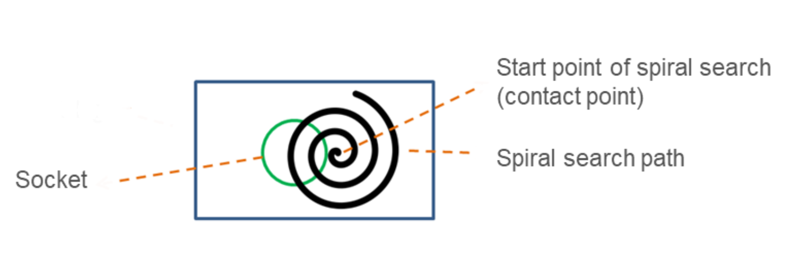
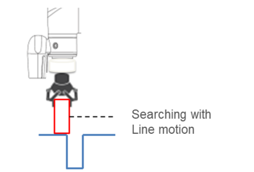
After completing the approaching step, the process enters the searching step. The searching stage can be carried out using two strategies: Spiral and Line. The following diagram illustrates the motion pattern of the spiral strategy. This search strategy uses the contact point established during approaching as the center of the circle. It searches outward in a spiral motion from the contact stop point where the insert and receiving part make contact during the approaching phase, continuing until the stop condition is met. If the user chooses the linear (Line) search method, the robot will follow the user-defined search axis to perform a straight-line search until the stop condition is satisfied, as shown in the diagram. No matter the search method. No matter if you are using spiral or line as the search method, the robot applies a fixed downward force along the Tool Z axis to maintain contact force.
The stop conditions for searching can be categorized into “search completion” and “search termination”. Search termination refers to the determination that no insertion point is found within the search criteria, such as if the search time is too long or the search distance is too far. Conversely, if the insert reaches the insertion point and the resultant force in the X-Y plane exceeds 5 Newtons (N), with zero Z-axis contact force, it is considered search completion, and the process proceeds to the final insertion stage.
The “search termination” condition is determined when, within the search criteria, no insertion point is found due to excessively long search time or excessive search distance. On the other hand, if the insert reaches the insertion point and the resultant force in the X-Y plane exceeds 5 Newtons (N), with zero Z-axis contact force, it is considered search completion, and the process proceeds to the final insertion (Inserting) stage.

When the resultant force in the XY plane exceeds 5 Newtons, it is determined to be the completion of the search.
Search Parameter Settings: Spiral #
In the spiral (Spiral) search, you need to configure the following parameters: Searching Radius, Circling Frequency or Tangential Speed, Height Tolerance, and Time Out. The table below provides definitions and explanations for each setting condition.
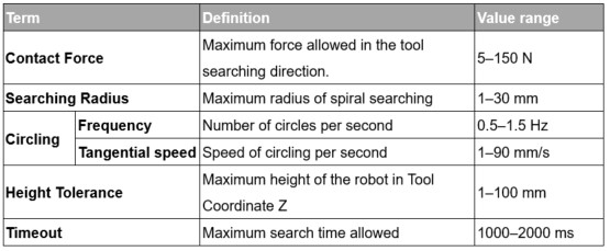
Please note that during the spiral search process, the robot may move beyond the boundaries of the receiving part, leading to a false detection of finding the insertion point. To prevent this misjudgment, setting a maximum allowable height variation can help avoid such occurrences.
Generally, if the geometry of the insert is circular, such as a locating pin, it is recommended to use the spiral search method. On the other hand, if the insert’s geometry is rectangular, such as an SD RAM, it is advised to set the search method to linear.

Search Parameter Settings: Line #
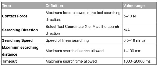
Line search settings have a parameter interface as shown in the diagram below. Unlike spiral search, linear search allows for the setting of the contact force magnitude along the tool coordinate system’s Z-axis (Contact Force) and the direction of the linear search (Searching Direction). The definitions of line search parameters are provided in the table below.
Plug-in #
After completing the searching step, the insert is aligned with the insertion point. During the plug-in process, the robot moves along the Z-axis until a stop condition is met, such as detecting Z-axis contact force or reaching the specified plug-in distance. If external forces are detected in the X, Y, RX, RY, or RZ directions during plug-in, the Smart Insert node will automatically move in a compliant manner in the opposite direction of the detected forces to avoid collision interference during the insertion process.
Plug-in Parameter Setting
The parameter settings for plug-in are similar to those for linear search. Users can configure the contact force, pushing speed, maximum moving distance limit, and timeout for the plug-in process.
The definitions and settings for each parameter are as shown in the table below.