- Goal
- What is a Cobot Welding Solution?
- What is the Welding Node?
- Preparation
- An Example of the Welding Solution
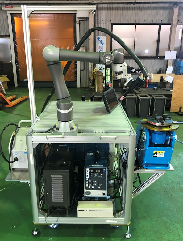
- Overview of the system
- Item#1 Robot and Cover
- Protection of Vision System
- Item#2 Power Source / Item#5 Wire Feeder/ Item#6 Torch
- Item#3 Teach Pendant
- Item#4 Table and Base/ Item#7 Flange Tool / Item#8 CO2 Tank and Welding Wire/ Item#9 Workpiece and Jig
- Item#10 Wiring & Integration
- Definition of I/O on TM Robot
- Manual Testing & Programming
- Example1 : Linear Welding
- Example2 : Linear and Circular Welding
- Real Welding
- Common Q&A
- Does TM support my welder?
- Could I use EtherCAT protocol with my welder?
- Does TM support welding type MIG/MAG/CO2/TIG?
- Does TM support weaving(zig-zag)?
- Does TM support seam tracking?
- Could I use robot to do thin part welding or Aluminium-based welding?
- Could I use vision job with Welding Node?
- Suggested welders that compatible with TM?
- What is the rotational speed?
- The definition of coordinate when using multi-layer function
Examples are valid for:
TMflow Software version: 1.88.2400 or later.
TM Robot Hardware version: HW3.2. (welding node supports HW3.0~HW3.2)
Other specific requirements: Refer to Preparation section below.
Note that older or newer software versions may have different results.
Goal #
This is a tutorial intended for system integrator(SI). In this article, we share the idea on building welding soultion with Panasonic power source(welder) for your reference. It’s not limited to the Panasonic welder, it could be any welder with similar functions.
The example below is not an official product from TM, please consult your welding expert locally about the welding equipment and welding knowledge.
What is a Cobot Welding Solution? #
It is a ready-to-use welding solution, normally with a Cobot on it and holding a torch for arc-welding process such as MIG/MAG.
EVERYONE CAN USE IT
Even an entry-level operator could teach and program the cobot with basic training, no more advanced robot programmer needed. Suitable for small and medimum-sized enterprise before large-scale investment.
TEACH BY HAND
Show the cobot where to weld, and start welding. To make welding easy!
LIGHT WEIGHT AND COMPACT DESIGN
Unlike industry robot, it’s possible to mount the cobot on a cart or magnet to get mobility. Thanks to the collabrative design of cobot, safety fence is no longer mandatory and this reduces the total cost of solution.
What is the Welding Node? #
A software welding package on TM robot.
The Welding Node is a software package especially for arc-welding application running on TMflow, the operating system of TM cobot. The Welding Node could be activatied by an add-on dongle provided from TM.
With the Welding Node, you could levergae following functions:
- End button actions for welding/move point teaching
- Specific setting UI for editing welding parameters
- Ready-to-use configurator for setting I/O to communicate with your welding machine

Preparation #
Before implementation, there are recommended items to study and prepare:
- Experienced in arc welding(or consult local welding expert)
- Welding & safety equipements for welding application
- Necessary protection for the robot and controller
- TM cobot with TMflow1.88.2000(or later) and HW3.2(HW3.2 for teach pendant)
- TM dongle with add-on license (welding node)
- Panasonic Welder 350VZ1, torch system, feeder and wiring
- PLC with analog output, wiring
Related manuals:
- TMflow Software Manual – for basic operation of TM cobot, could be downloaded at Download Center

- Welding Guide – manual for welding node, could be downloaded at Download Center
An Example of the Welding Solution #
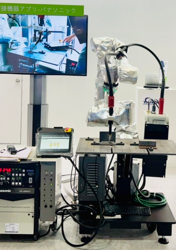
Overview of the system #
This is an example of leveraging Panasonic power source(general I/O) for arc-welding system . Please consult local Panasonic distributor for more infomation regarding to welding equipments and related manuals.
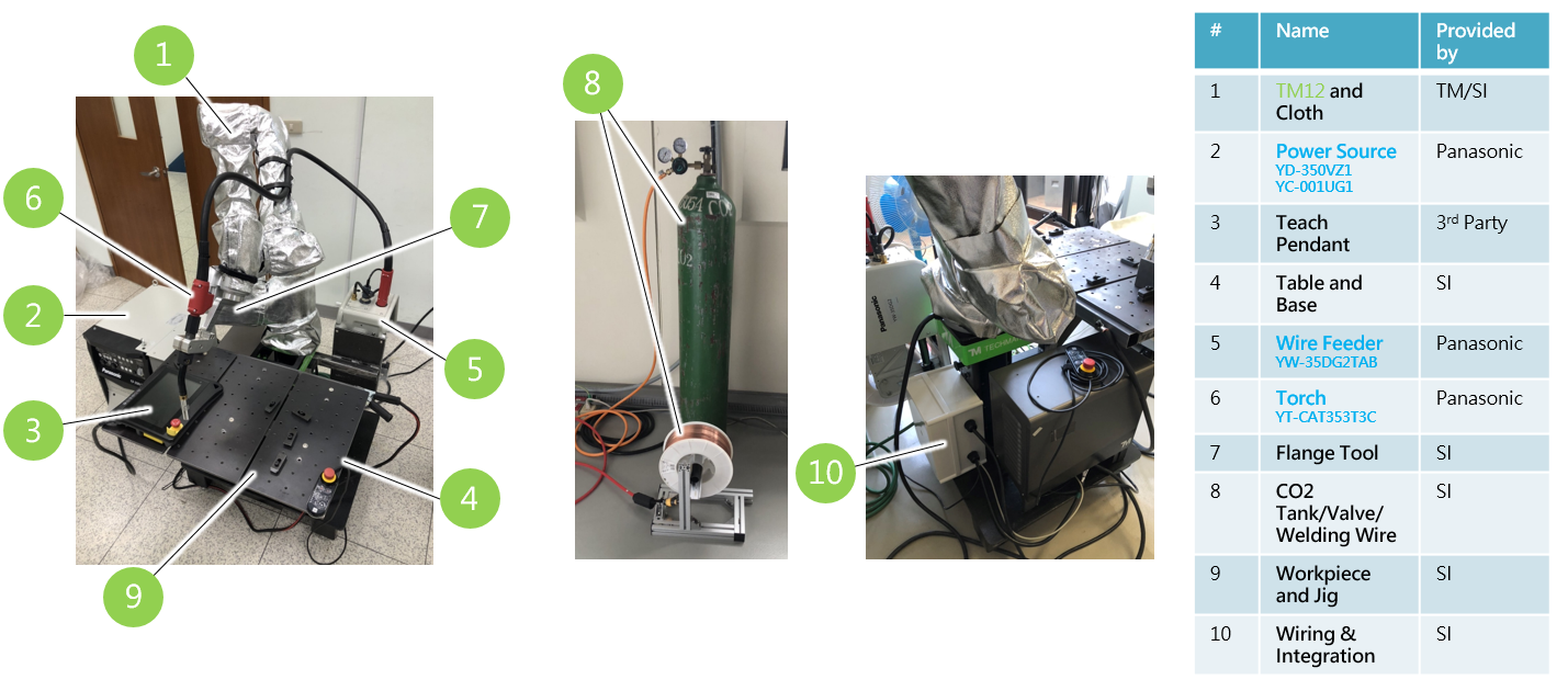
Item#1 Robot and Cover #
Protective cover is suggested to have on robot arm and controller to protect them from spatters, particles. It depends on how harsh the welding environment is.
TM12 is used is this example.
Products could be found on TM Plug&Play:
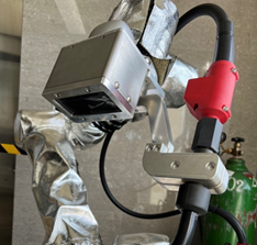
Protection of Vision System #
TM provides robot with and without vision camera on flange. If using vision system, it’s necessary to have filter to protect the vision system from direct UV damage in the camera.
There is the reference design for the protection if needed, download link : ![]()
Note that the AUTO UV FILTER MODULE could be found on market easily.

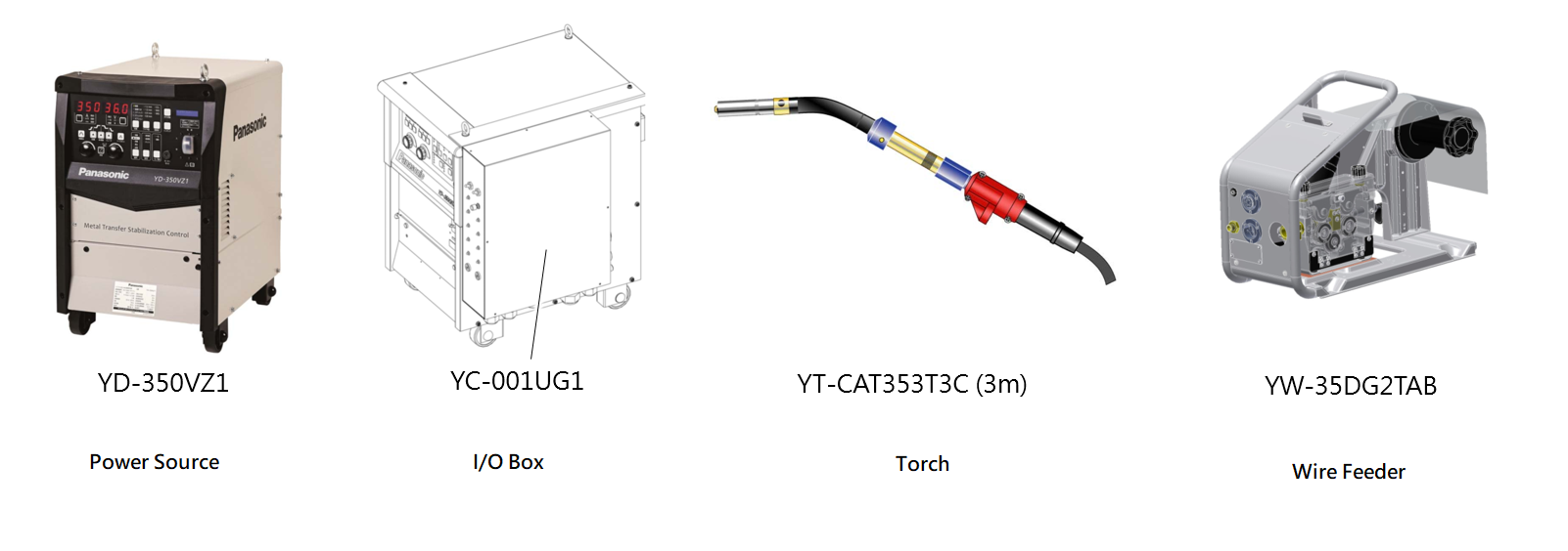
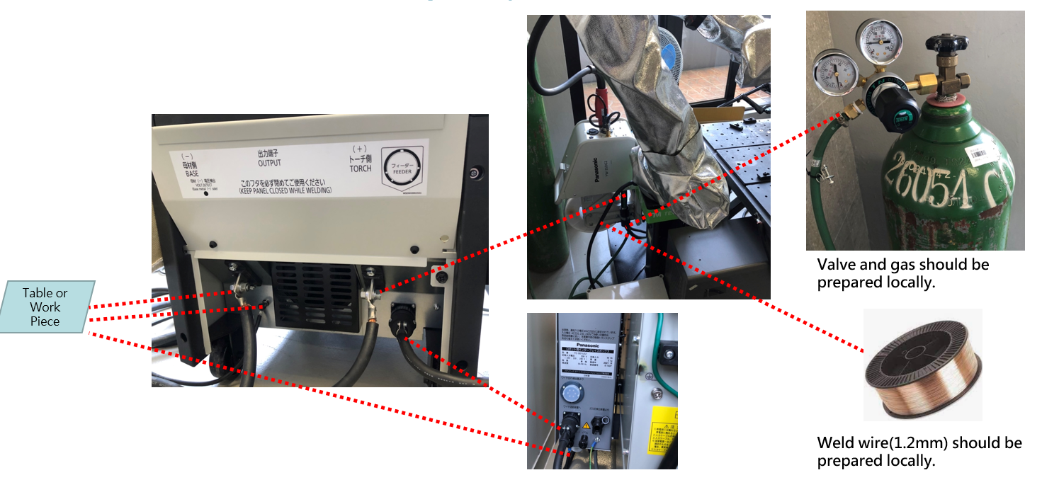
Item#2 Power Source / Item#5 Wire Feeder/ Item#6 Torch #
In this example, we used following standard parts from Panasonic:
- Power source YD-350VZ1 and YC-001UG1(I/O interface box)
- Torch YT-CAT353T3C
- Wire Feeder YW-35DG2TAB
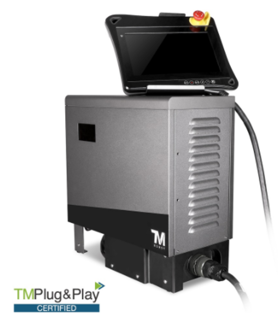
Item#3 Teach Pendant #
The optional teach pendant is a 3rd-party item. Please visit TM website -> TMplug&play if you’re interesting in it.
Item#4 Table and Base/ Item#7 Flange Tool / Item#8 CO2 Tank and Welding Wire/ Item#9 Workpiece and Jig #
Those items could be prepared by SI easily.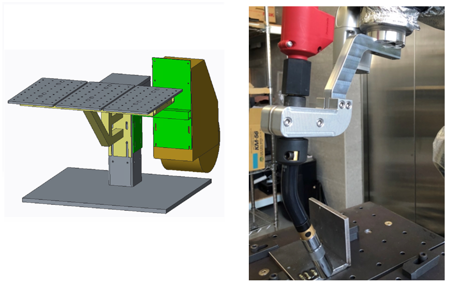
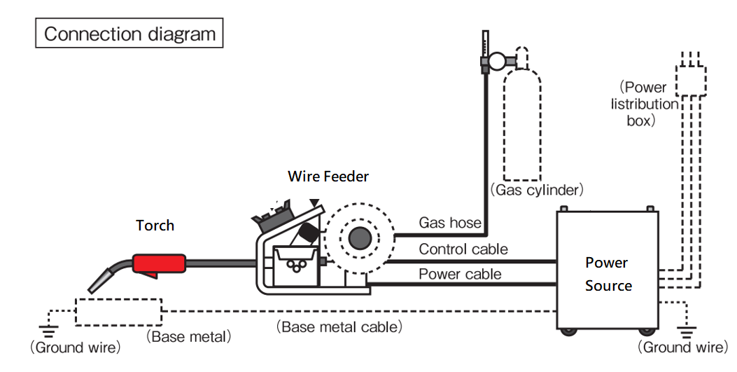
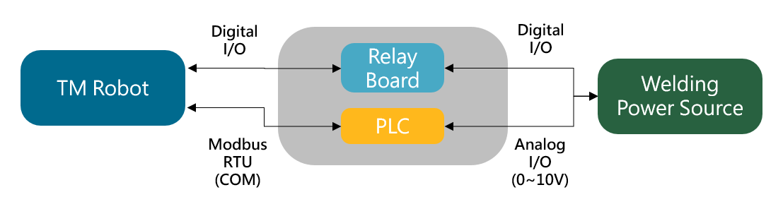
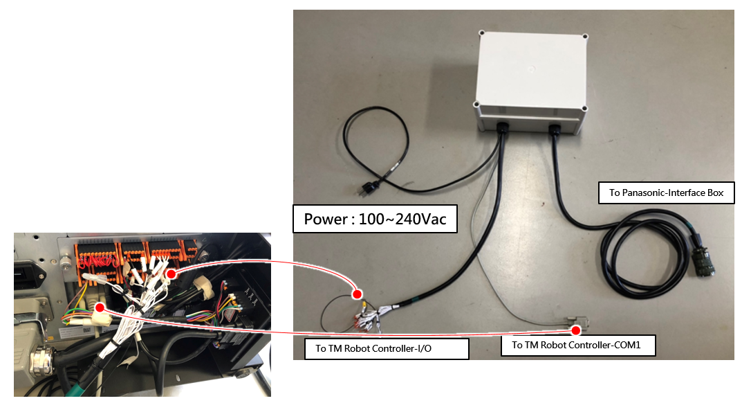
Item#10 Wiring & Integration #
For I/O connection between TM robot and the welder, there is a junction box needed to be implemented. Key components in the junction box are listed below:
- Delta PLC DVP20SX2 – to provide two analog singnals to control the welder, which is connected to TM robot controller through Modbus RTU(marked as COM in the circuit diagram below), could be replaced with similar PLC.
- Relay Board – the dry contact to isolate digital signals
- 24V Power – power the PLC
- Terminals – for wiring
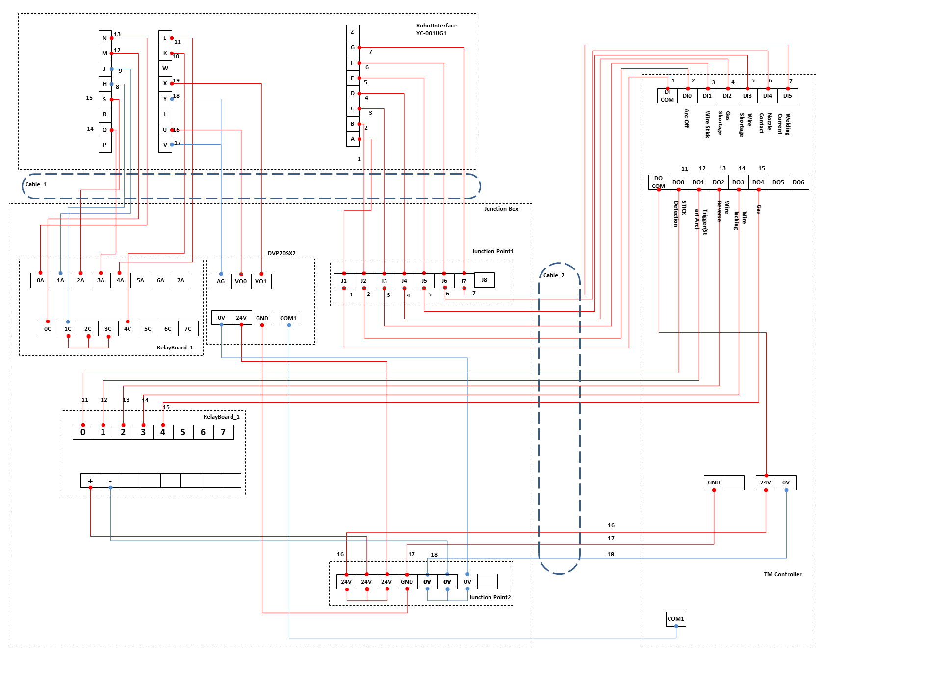
There is the wiring between TM robot and welding power source. For PLC, program the logic to receive commands on Modbus RTU and mapping it to two of analog outputs to control the current and voltage(0V~10V) on the power source.

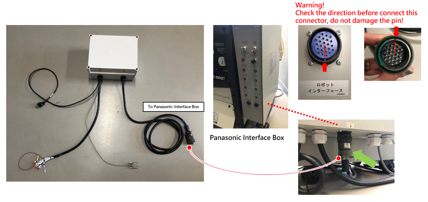
Finish the wiring for the power source, please refer to Panasonic manaul for more information:
Detailed wiring scheme:
PLC could be replaced with external ModbusTCP device:
Related materials:
- How To Add IO Channels With External IO Device Via MODBUS TCP/IP? – for adding external I/O devices on Modbus, refer to Technical Documents
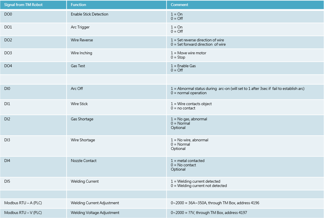
Definition of I/O on TM Robot #
Once the hardware wiring is done, we could control the power source by following I/O definitions on TM robot.
It’s not fixed to the definition below. Modify it to fit your welder.
Check the connection with care before powering up the welding power source and TM robot.
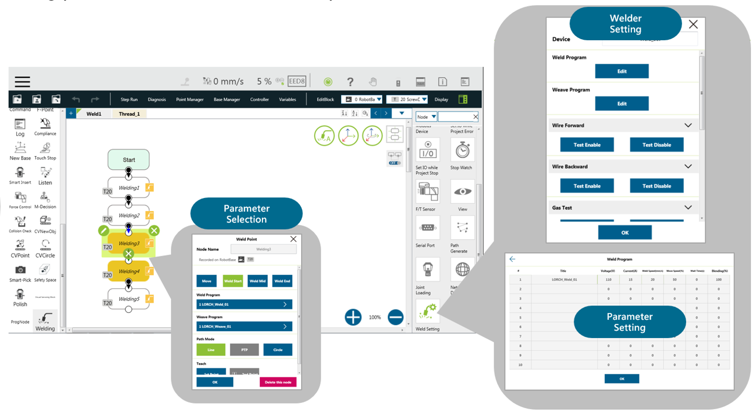
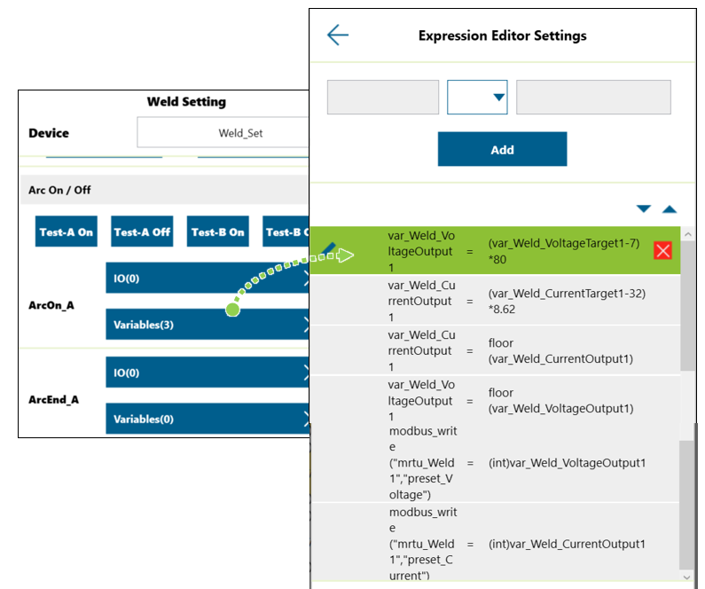
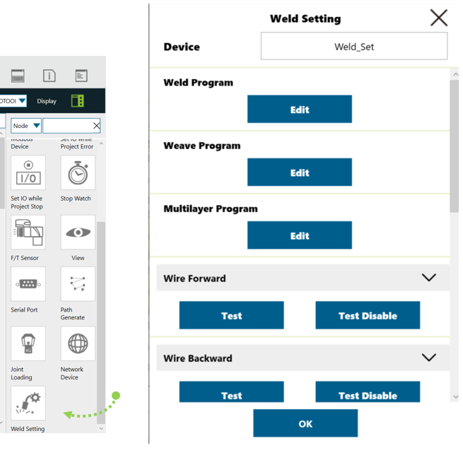
Please set necessary signals in Welding Setting->ArcOn/Off Event and Manual Test in TMflow. Refer to manual Welding Guide for more information.
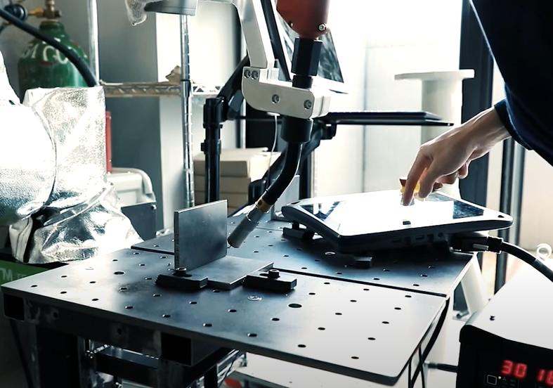
Manual Testing & Programming #
Test the following steps before real welding:
- Gas On(DO4), Wire Inching(DO2/DO3)
- Arc Trigger(DO1)
- Welding Current(DI5)
- Voltage/Current Command(Modbus RTU-V/A)
- Teach the welding path and welding nodes
- Set the signals(Arc Trigger for example) when robot stops in TMflow->Set I/O while Project Stop to cut the power when error happens
- Test the cut-off function when the robot gets error during welding or stops
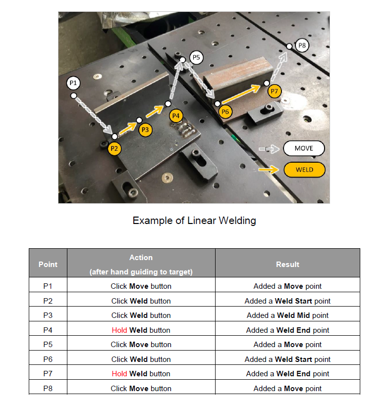
Example1 : Linear Welding #
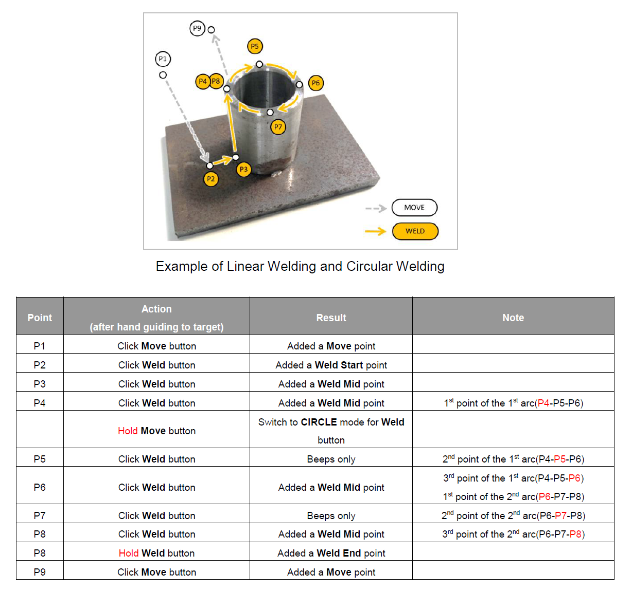
Example2 : Linear and Circular Welding #
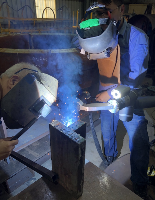
Real Welding #
Check the safety equipments and environment such as welding mask, fire extinguisher and so on before real welding.
Run the TMflow project carefully.
Common Q&A #
Does TM support my welder? #
General I/O (digital + analog) are very common on most welders on the market. Panasonic 350VZ1 in this tutorial is one of them.
It’s not limited to specific brand of welder.
Could I use EtherCAT protocol with my welder? #
No.
TM robot supports following connections:
- General I/O
- Modbus TCP/RTU (partial functions supported, refer to manual Welding Guide for more information)
If the welder uses EtherCAT/Profinet Scanner/Ethernet/IP Scanner/DeviceNet/CCLink…etc., it’s not supported by TM robot.
Does TM support welding type MIG/MAG/CO2/TIG? #
There are different processes related to arc welding such as MIG/MAG/CO2/TIG. It depends on the type of welders, not the robot.
TM robot could control the welder if the connection is supported by TM, no matter it is MIG/MAG/CO2 or TIG, and even laser welder.
Please note that if TIG is using, make sure that the isolation between torch and robot flange is good enough and also the whole grounding should be considered well at the welding feeder side since there will be high frequency noise during TIG welding.
Does TM support weaving(zig-zag)? #
Yes, weaving and multilayer are standard functions in welding node.
Does TM support seam tracking? #
No, it’s not supported in current version of welding node.
Could I use robot to do thin part welding or Aluminium-based welding? #
Yes if the welder supports. Consult your welding machine vendor for more information.
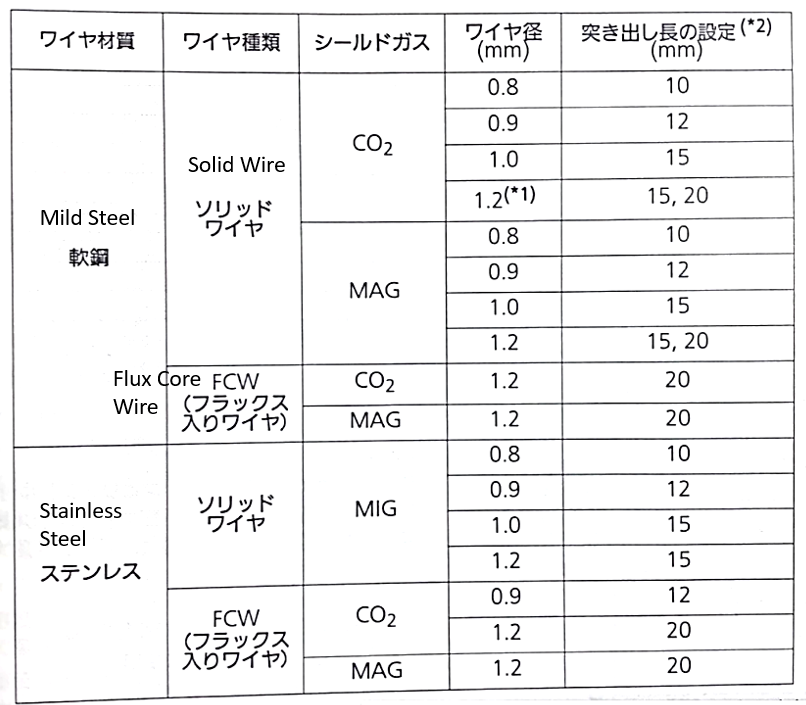
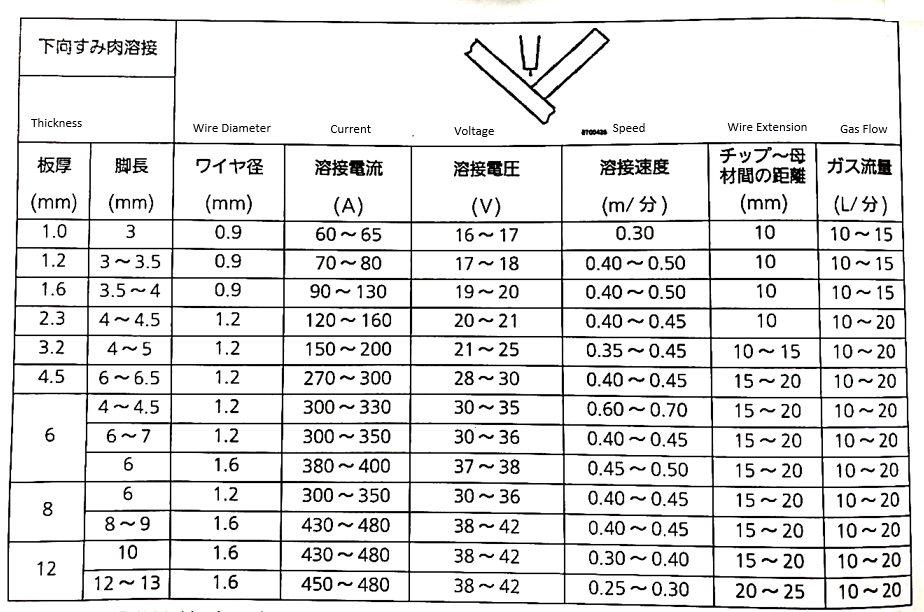
Take Panasonic 350VZ1 welder for example, it supports welding material such as mild steel and stainless steel, from thickness 1~12mm in following welding condition from the manual:
Could I use vision job with Welding Node? #
Yes, functions in TMvision vision job could be used together with Welding Node such as landmark positioning or object positioning.
Suggested welders that compatible with TM? #
It’s not limited to specific welders but there are numbers of welders that are already connected with TM. Please contact to local distributors for more information.
| Maker | Package | Interface with TM |
| Panasonic | YD-350VZ1(power source)
YC-001UG1(I/O interface box) YW-35DG2TAB(feeder) |
I/O |
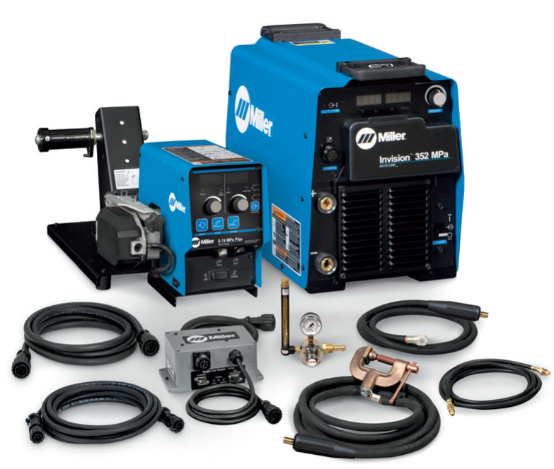
| Miller | Invision MPa Plus Cobot System
Cobot Interface(I/O interface box) S-74 Feeder |
I/O |
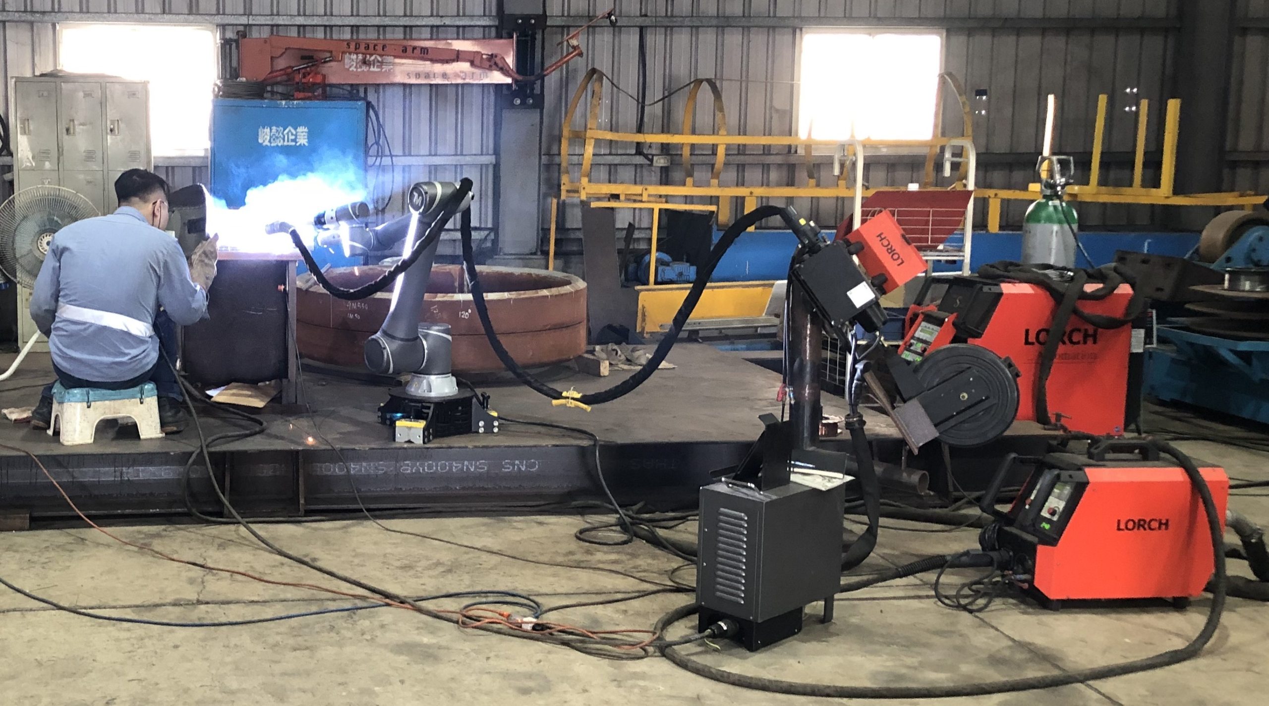
| Lorch | S-series LorchNet-Modbus TCP module Feeder |
I/O
Modbus TCP |
| DAIHEN | Welbee A350P
HC-71D(feeder) |
I/O |
Panasonic
Miller
Lorch
DAIHEN
What is the rotational speed? #
In welding node, we introduced a new parameter Rotational Weld Speed:
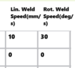
A movement is consisted of linear movement and rotational movement. So we need to define linear speed and rotational speed to tell the robot to move. Then, why rotational speed does not exist before? Because it always has been set to a default value, but we put it in the welding node in case you need to change it.
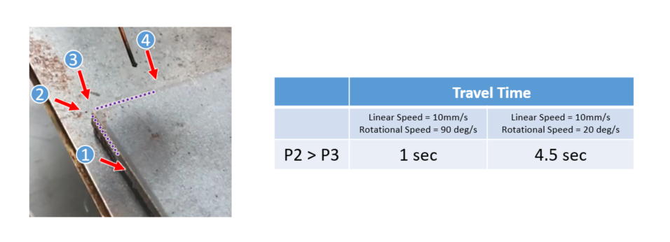
Here is an example to use the rotational speed:
Left: linear speed = 10mm/s, rotational speed = 20 deg/s
Right: linear speed = 10mm/s, rotational speed = 90 deg/s
When it move from P2 to P3, it is a pure rotational movement(that is, no linear movement), so linear speed does not affect the result, but rotational speed does! So you can modify rotational speed to adjust the travel time or speed at the corner, that will affect the welding result.
There are more examples when combine linear and rotational movement: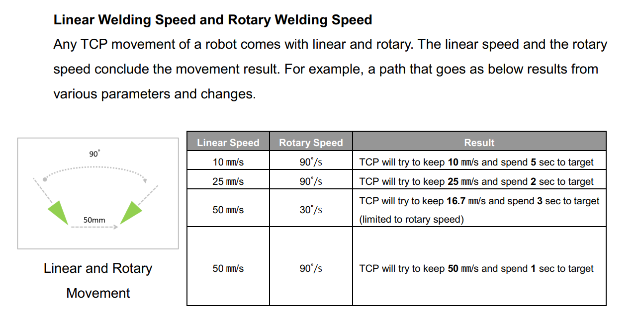
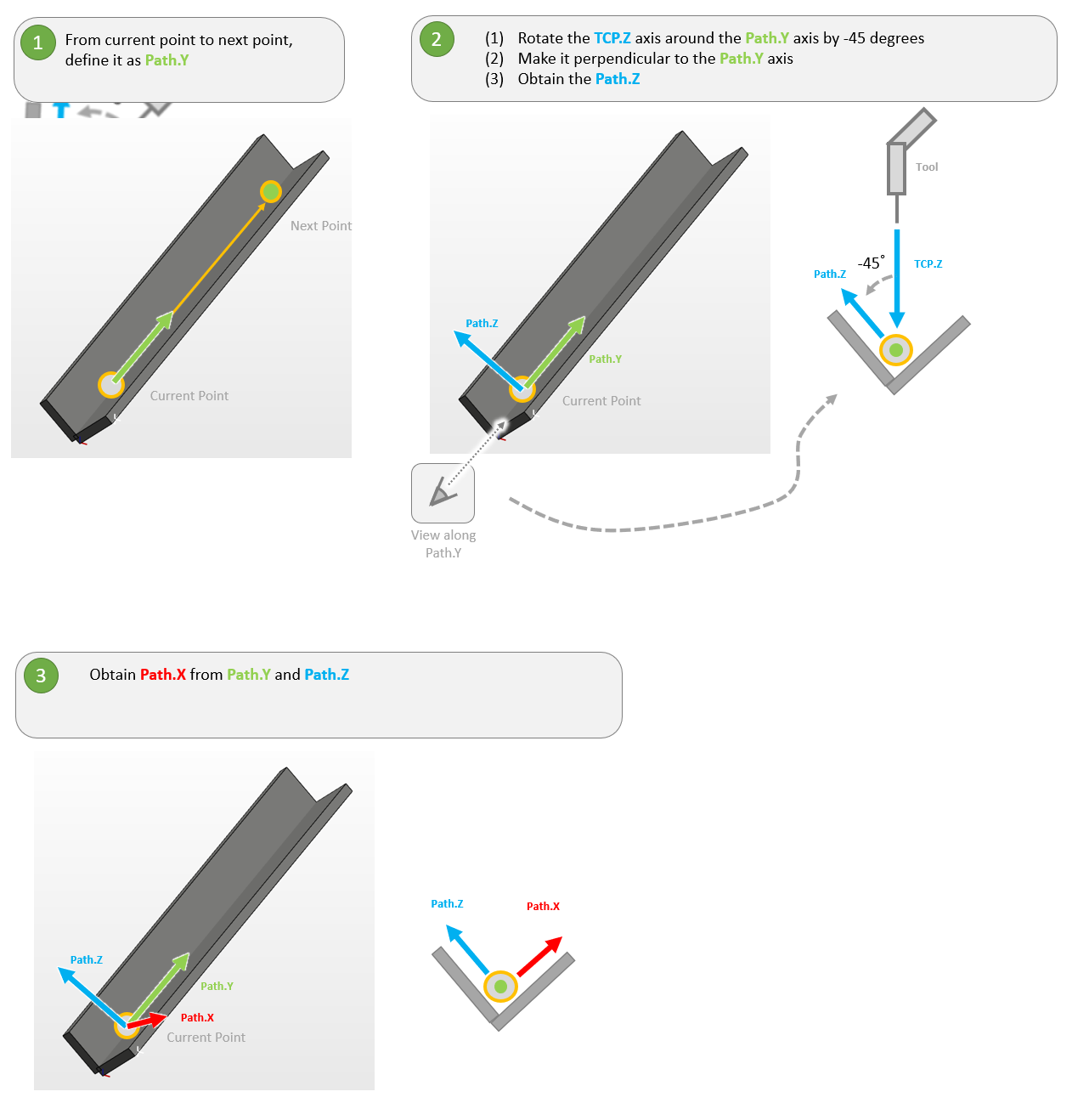
The definition of coordinate when using multi-layer function #