Examples are valid for
TMflow Software version: 2.16.2200 or later
TM Robot Hardware version: HW3.2 / HW5.x
Other specific requirements: No.
Note that older or newer software versions may have different results.
Goal #
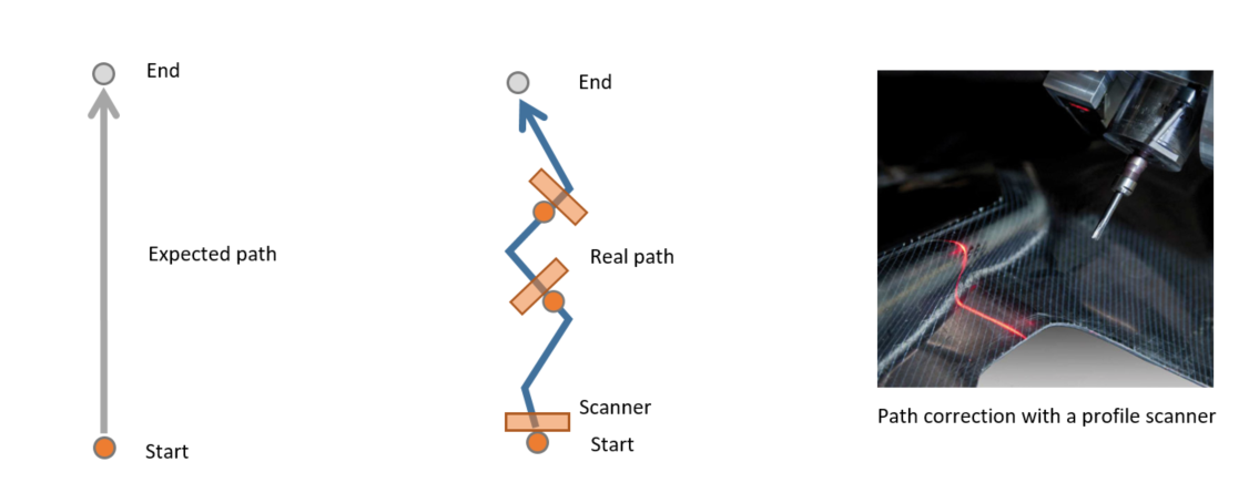
In applications such as deburring, welding, gluing, you might need the robot to correct its path automatically based on the uncertain path.
You can teach the expected path in TMflow Project and then make the near real-time correction(less than 8Hz) in TMflow Thread with Path Offset. For example, follow the curve on the surface.
Path Offset is a new function sets in standard TMscript in TMflow 2.16.
Preparation #
- TM robot with TMflow2.16.2200(or later)
- External input device(laser scanner, analog input device, etc.)
- Build communication between robot and your device
- Make sure you have correct TCP and Base
Related Manual #
- TMflow Software Manual – for basic operation of TM robot, could be downloaded at Download Center

- Programming Language TMscript (for TMflow 2.16 and later) – manual to use Path Offset, could be downloaded at Download Center
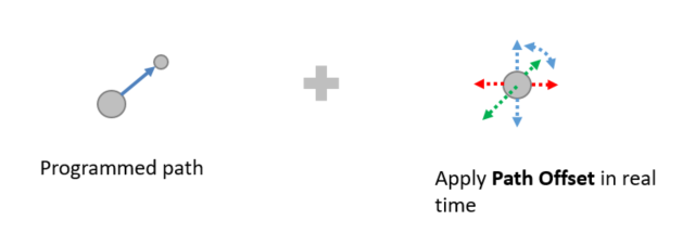
Path Offset #
The concept of Path Offset is to correct the path in real time with given data in 6 degrees, that is [x, y, z, Rx, Ry, Rz]:
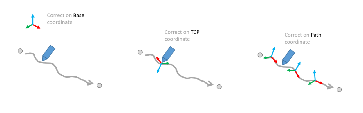
In addition, you can assign different coodinate systems with TMscript function PathOffset_Set():
Hint
Also, the response speed of the tracking system could be adjusted with TMscript function PathOffset_AlphaFilter(). From 0~1, lower the value will lower the response speed. Always start testing from low value such as 0.01 to prevent jerking. Read Programming Language TMscript(for TMflow 2.16 and later) for more information.
Example1 : Path Tracking System #
In this example, a 3rd-party laser scanner MicroEpsilon scanCONTROL 3060 is connected to the robot. It measure the path offset in advance and then send it to robot for correction.
Robot follows a given path from p1 to p2, then applies path correction in near real-time.
Path correction is NOT limited to laser scanner used in this example. The feedback data can be retrieved from any device that communicates with robot, such as an analog button, a force sensor, etc.
Here is the system diagram: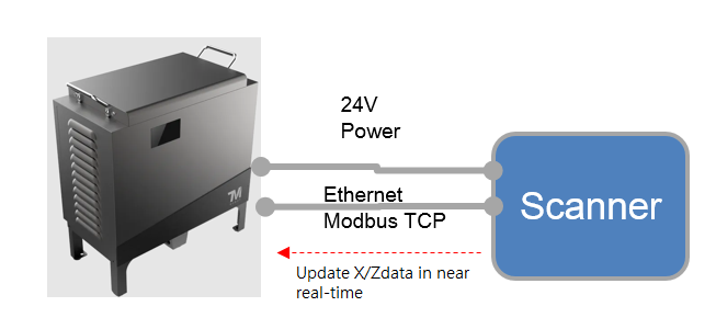
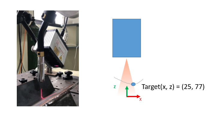
What can a laser scanner do? #
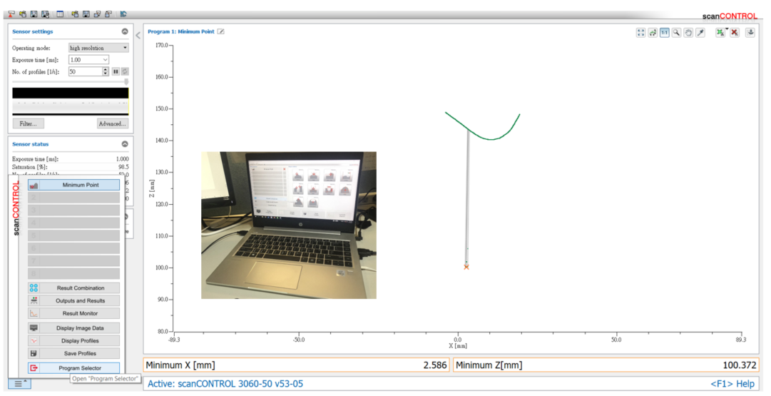
A typical 2D laser scanner can measure a profile on a surface, and send out the continuous profile data as a array in near real-time. It might also calculate the interesting point(such as the position of lowest point as shown below) and send to robot directly.
To configure the scanner, you will need the tool scanCONTROL from MicroEpsilon Please contact them for more information.
Programming #
Create a new TMflow project with main flow and a thread as below: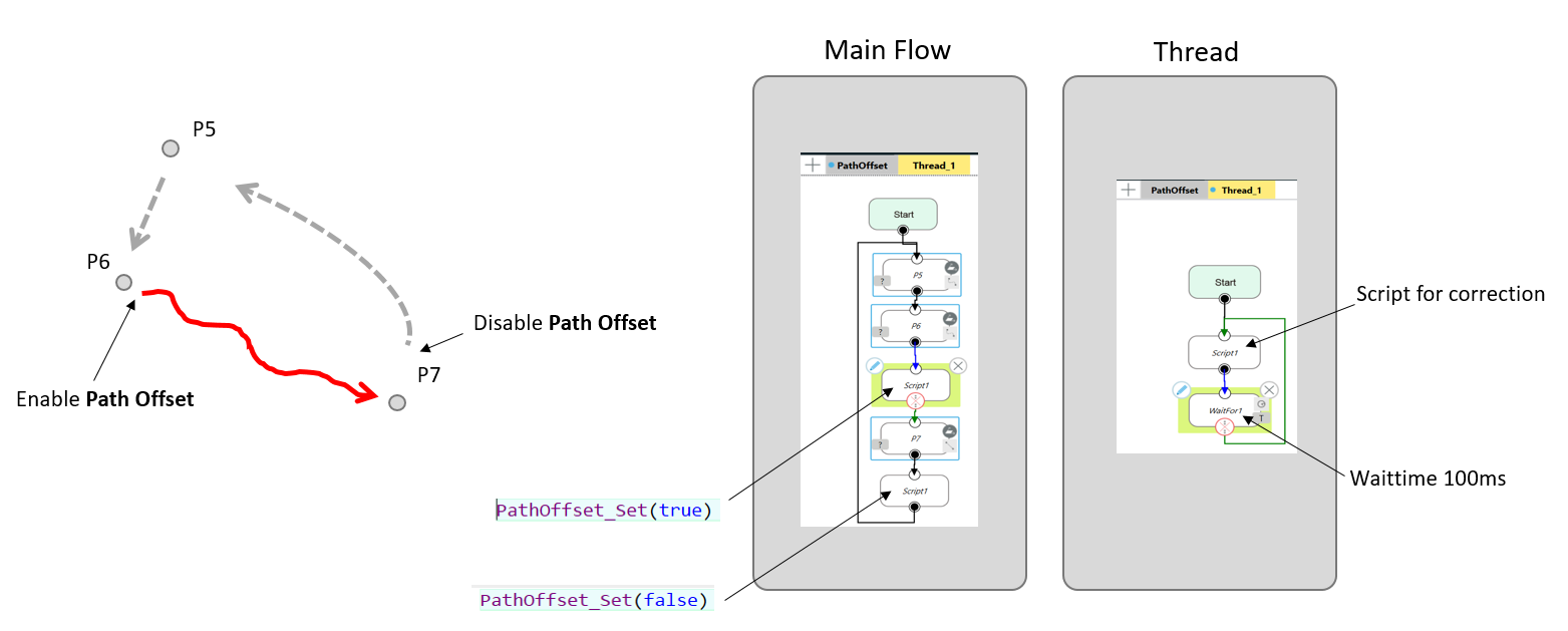
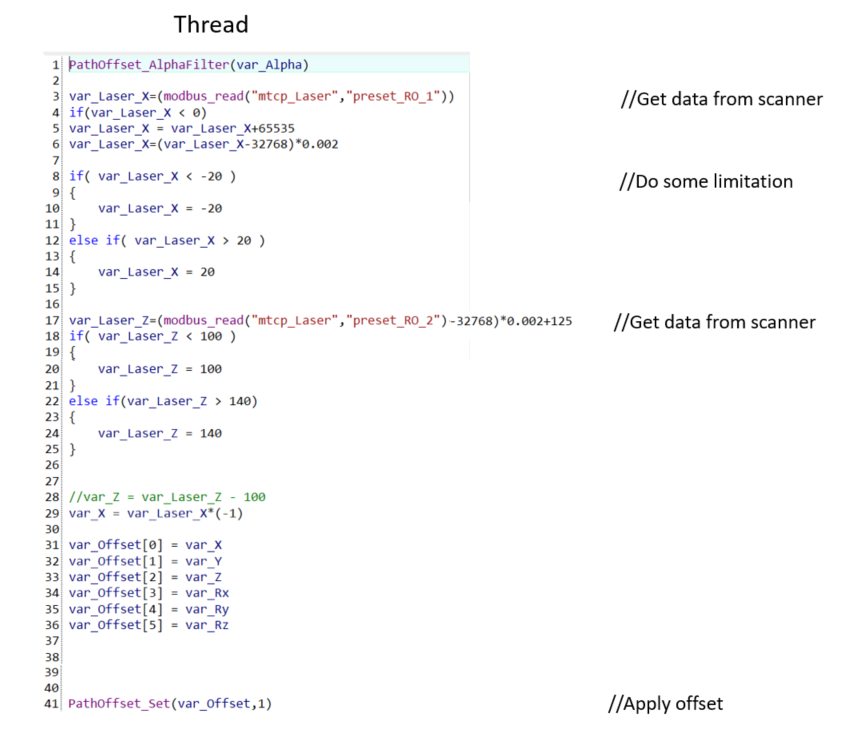
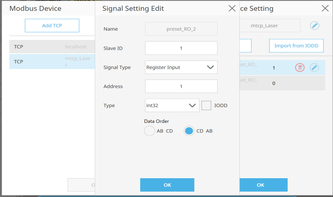
Modbus setting in this example, two signals for offset_x and offset_z from the scanner:
Then you can run this program, it will try to follow the path.
Notice #
Please note that the data stream from scanner is in advance of TCP path. Implement your algorithm to store and adjust the data and calculate the delay between scanner and TCP position.
Example2 : Surface Tracking System #
With the same laser scanner in Example1, the robot can keep the distance between target and TCP. It might be useful in continuous process such as gluing or dispensing on variant tartgets. The function of Path Offset could be used even when the robot is stationary.
Example3 : How Fast It Can Track? #
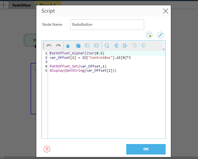
In this example, we connect a analog variable resistor(output : 0-10V) to an analog input channel on robot. The robot will try to track the target while rotating the button.
The programming in this example is relatively simple:
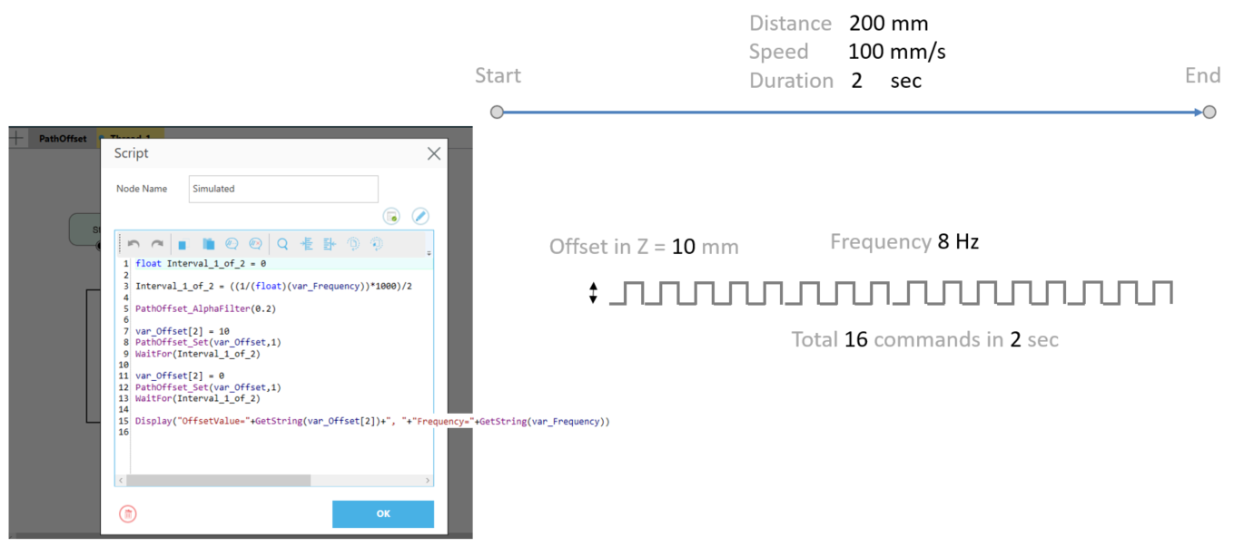
Simulated Command #
To make it more data-driven, we create a command generator in Thread. It will generator 16 commands within 2 sec when robot travel from start point to end point.
- Command frequency : 8 Hz
- AlphaFilter : 0.2
- Distance of each offset : 10mm
If the incoming command is faster than this frequency, the robot won’t be able to track it.