Use Force Control Node to Assist Material Insert Application
Updated on 2026 / 08 / 27
Examples are valid for:
- TMflow Software version: All versions with Force Control Node.
- TM Robot Hardware version: All versions.
- Other specific requirements: Force sensor needed.
Note that older or newer software versions may have different results.
Background Information
This article will demonstrate an example of using force control node to assist material insert application. In this example, we use force sensor to detect the resist force from different direction while inserting, then Force Control Node will adjust robot posture according to the force detected. Users could try this method if they have difficulties to perform robot material insert straight in to the bottom.
Please be aware, a TM supported Force sensor is needed to use Force Control Node.
Parameter Setting
| 1. Please drag a Force Control Node to project, and click on the pencil icon on Node to edit it. | 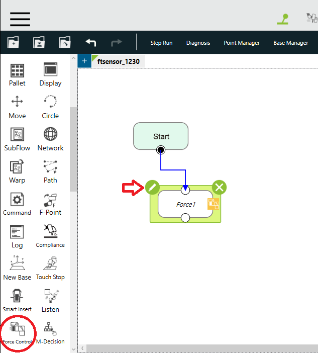 |
2. (A) Choose force sensor in list. If you don’t add a sensor yet, you could add it now.
3. (B) In this example, we use Setpoint F/T method. To set more parameters, click on the button. | 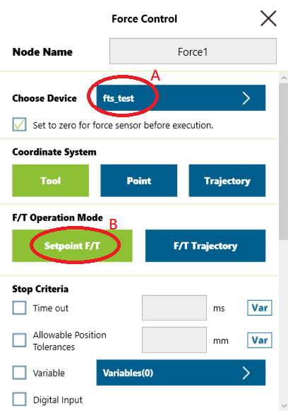 |
4. (C) Clicking on the check box of Fz will let robot adjust movement while Fz force detected. And vice versa for Fx, Fy, Tx, Ty and Tz. User can combine different
5. (D) By entering a number in the text box, it will give robot an initial force with the designated direction.
6. (E) By adjusting the drag bar to the left, the needed force to trigger the robot movement will be higher. On the other hand, if the scroll bar is adjusted to the right, the needed force to trigger the robot movement will be lower.
| 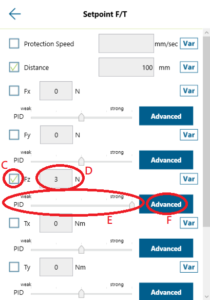 |
| 7. (F) User can click on advance button to set PID by themselves ,but the value of scroll bar(strong/weak) will be omitted if Kp is modified here. Please make sure to test the setting in a small interval every time because inappropriate setting might cause robot to overreact, which causes a potential collision. | 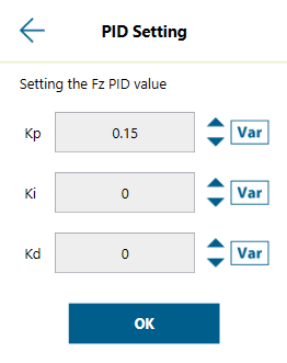 |
Parameter adjustment video illustration :
| Step 5 | Kindly refer to the video in the attached file titled “Step 5.” |
| Step6.1 drag to left | Kindly refer to the video in the attached file titled “Step 6.1 drag to left .” |
| Step6.2 drag to right | Kindly refer to the video in the attached file titled “Step 6.2 drag to left .” |
Test Result
The tool used is the cylinder with diameter of 7mm, and the hole going to insert into is 8mm in diameter.
The setting of Force Control Node is as below.
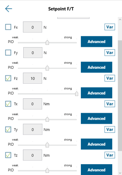
I checked Fz, Tx Ty and Tz because I expect the insert movement will be facing resistance force from those direction, users could adjust according to your scenario.
With 5 degree offset in Rx direction, Force Control Node help robot to insert the cylinder to the hole
Kindly refer to the video in the attached file titled “Video-Result .”
If the offset angle is higher, user could try to adjust different parameter combination.
More Example
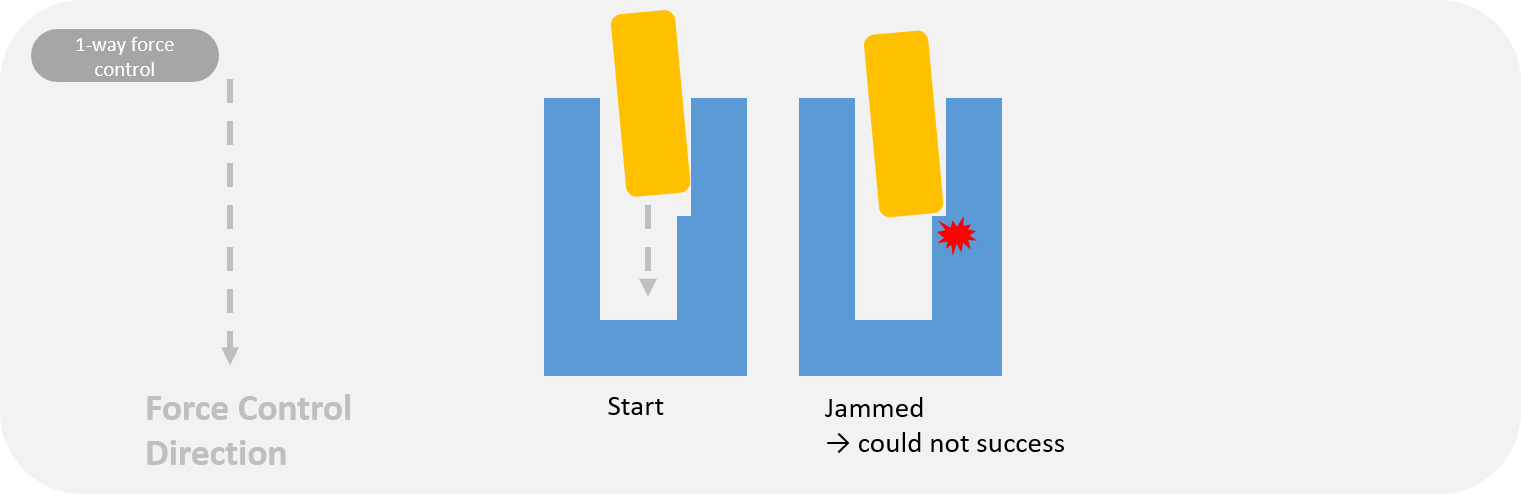
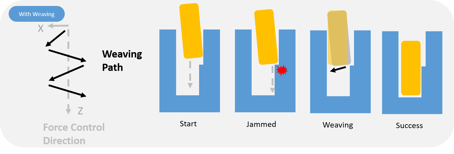
In some corner cases, the object might be jammed.
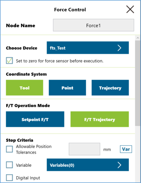
To overcome this issue, weaving could be added to the path of F/T Trajectory mode to create X direction weaving or even X-Y direction weaving.
|  |
| 2. Set on the parameter | 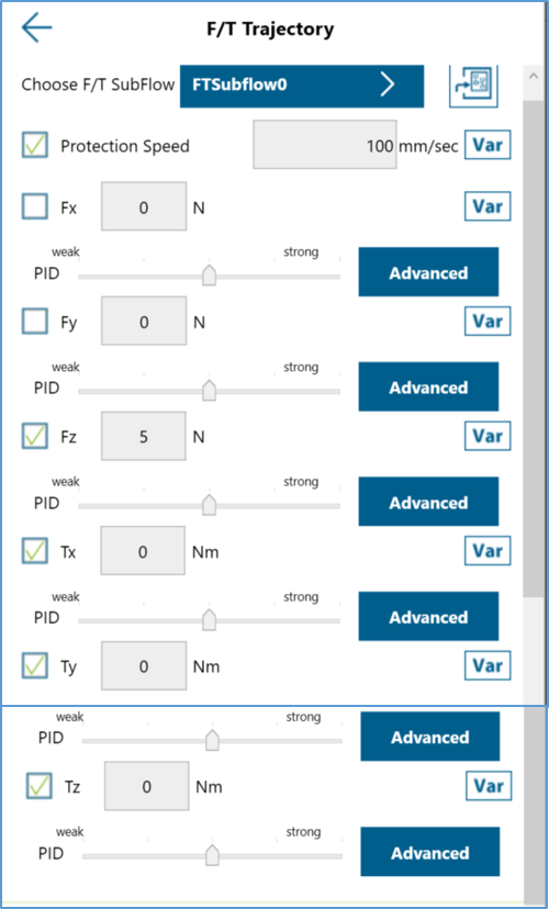 |
| 3. Create a F/T Subflow and program it | 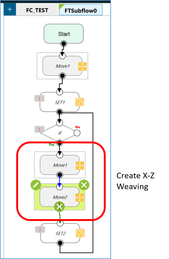 |
Result can be seen in the video in the attached file
- If no force control applied, the object will be jammed at the beginning.
- X direction weaving in dry run
- X direction weaving in action
Was this article helpful ?