How to Re-Establish 3D ETH Relationships After Movement
Updated on 2026 / 03 / 24
Examples are valid for :
TMflow Software version: All versions
TM Robot Hardware version: HW3.2 or above versions
Other specific requirements:
• 3D camera
• Landmark
• Robot with 2D Camera
Note that older or latest software versions may have different results.
Purpose
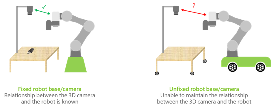
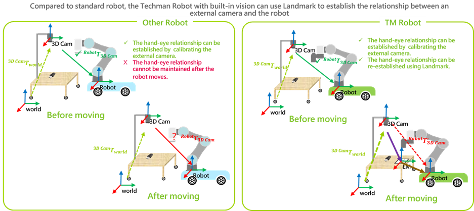
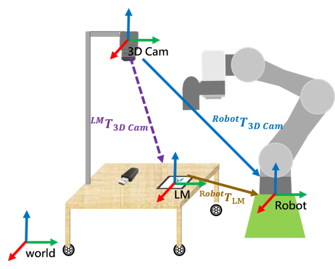
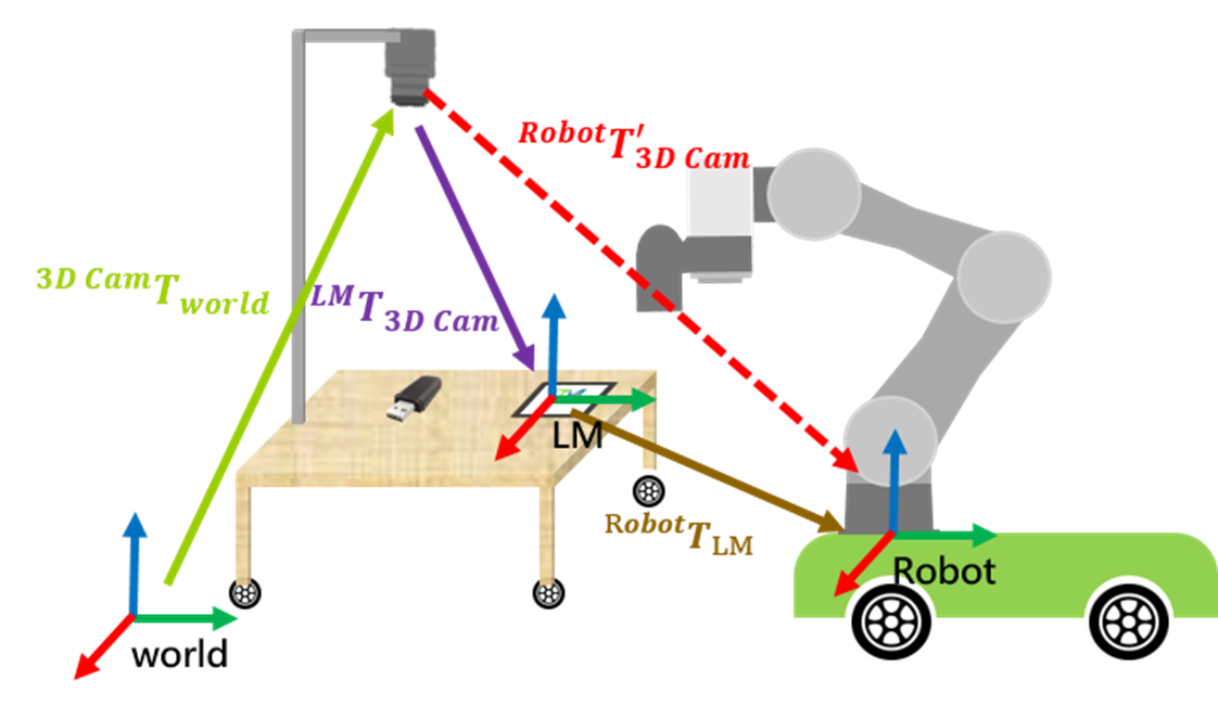
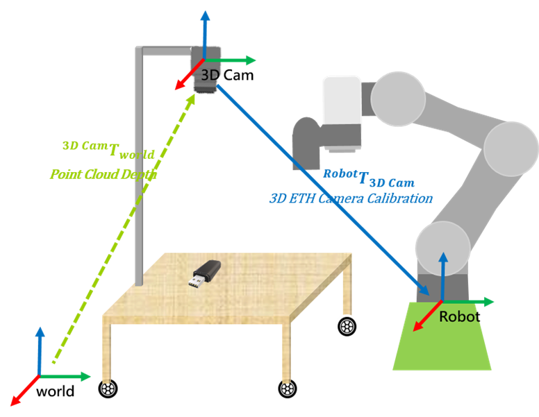
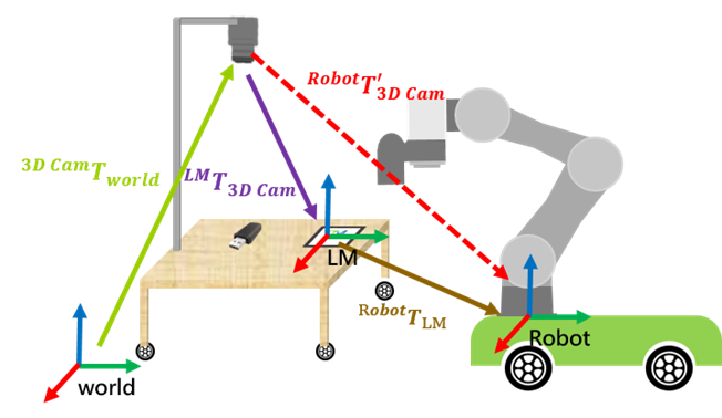
• We can establish the relationship between the robot and the 3D camera through ETH calibration, as illustrated by the green line in the figure below.
• If the robot or the table is moved, this will alter the relationship between the 3D camera and the robot, as shown by the red line in the figure below. In this case, the relationship becomes unknown.
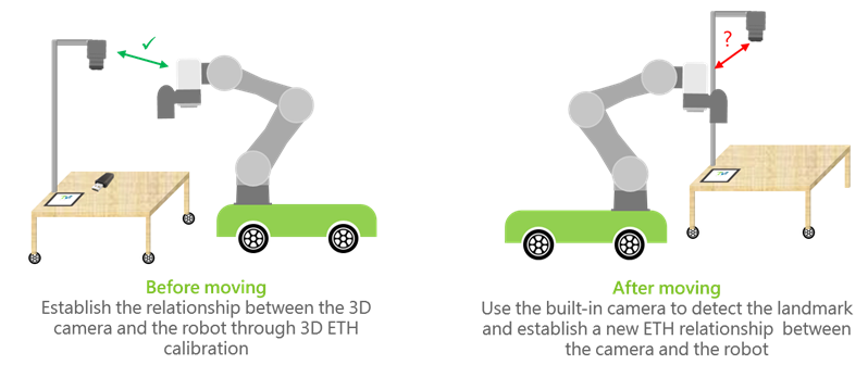
• At this point, we can fix a landmark at one corner of the table and use the position of the landmark to re-establish the ETH relationship between the 3D camera and the robot.
Definition of Symbols
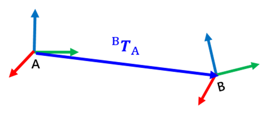
- BTA represents the transformation relationship from A base to B base.
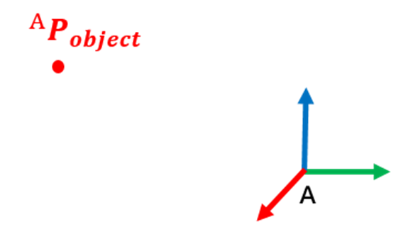
- APobject represents the position of an object in A base
Advantages of Built-in Vision for the Robot
Base Transformation Relationship
Fixed Robot Base/Camera
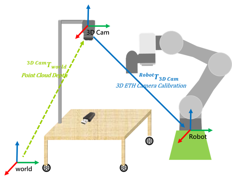
Under normal circumstances, we can obtain the relationship RobotT3D Cam (3D ETH Camera Calibration)through ETH calibration, which defines the workspace.
- Through vision job in TMflow, we can obtain RobotPobject, which represents the position of the object in the Robot Base.
- At this point, the relationship 3D CamTworld is unknown in TMflow. We need to derive 3D CamTworld using RobotT3D Cam and RobotPobject. This derived relationship describes the object’s pose in the 3D Camera Base.
- The relationship is as follows:

Before Moving- Unfixed Robot Base/Camera
• Place the landmark at a fixed position on the table.
• Next, create a vision job to locate the landmark and obtain the Vision Base of the landmark, denoted as RobotTLM. . The relationship is as follows:

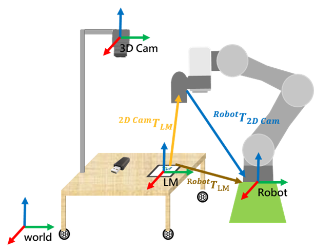
- At this point, RobotT3D Cam and RobotTLM are known. To obtain the hand-eye relationship after moving, we must first determine the relationship LMT3D Cam before moving. The relationship LMT3D Cam is as follows:

After Moving- Unfixed Robot Base/Camera
- Base on the settings before moving, the relationship LMT3D Cam is already known. After moving, capture the LM again to obtain the new relationship of LM relative to the Robot RobotT'LM. . Combing RobotT'LM , we can derive the new workspace after moving, which is RobotT'3D Cam . The relationship is as follows:

- Using the relationship RobotT'3D Cam in combination with 3D CamTworld , we can transform the object in the World Base worldPobject to the new Robot Base, which is RobotP'object . The relationship is as follows:

TMflow Configuration
Vision Job Localization
• After completing the ETH correction, it is necessary to instruct the picking position.
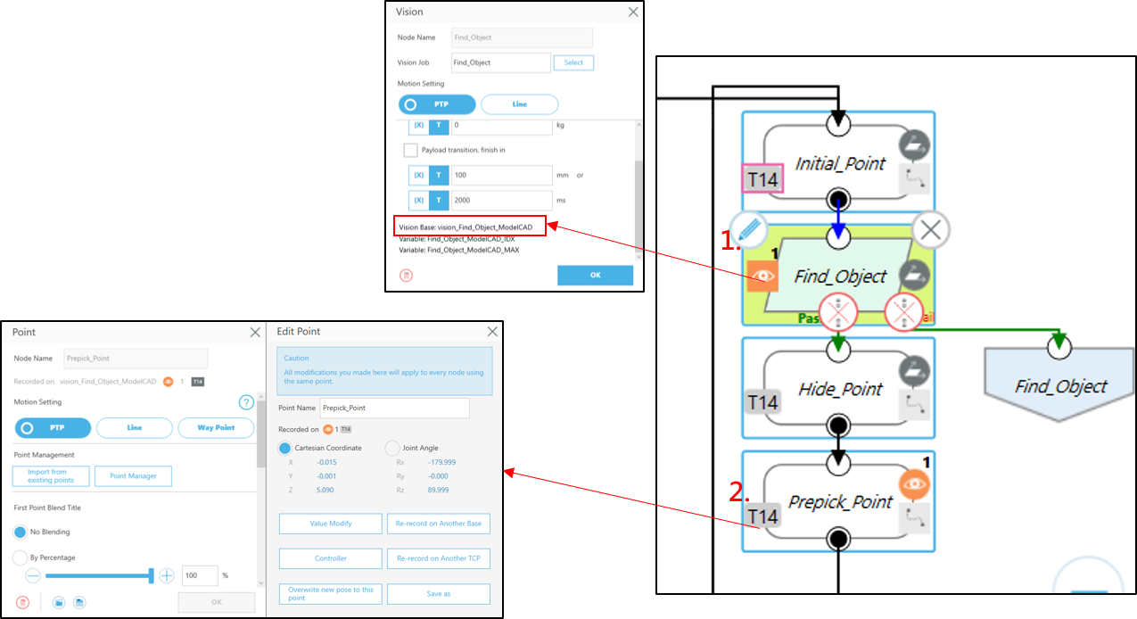
• In step #1, acquire the vision job object’s vision base and variable “Base[“Vision_Find_Object_ModelCAD”].value”.
• In step #2, teach the picking point “Prepick_Point” through the Vision base.
Fixed Robot Base/Camera
• Under normal circumstances, we can obtain the relationship RobotT3D Cam (3D ETH Camera Calibration) through ETH calibration, which defines the workspace.
• Through vision job in TMflow, we can obtain RobotPobject, which represents the position of the object in the Robot Base.
• At this point, the relationship 3D CamTworld is unknown in TMflow. We need to derive 3D CamTworld using RobotT3D Cam and RobotPobject.. This derived relationship describes the object’s pose in the 3D Camera Base.
• The relationship is as follows:

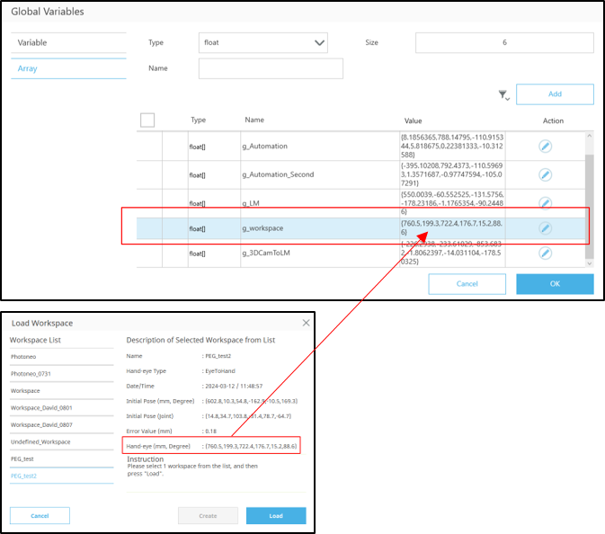
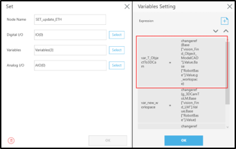
- Add a global variable “g_workspace” and record the calibrated ETH relationship in this variable.
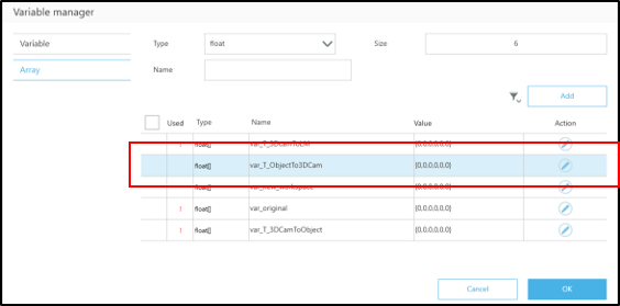
- Add the variable “var_T_ObjectTo3DCam” to describe the transformation 3D CamTworld.
- After the vision job object localization, connect a SetNode next
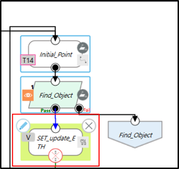
- Use the ‘changeref’ function to change the object's Vision base from Robot Base to describe it on the 3D Camera Base, and record this relationship in “var_T_ObjectTo3DCam”, which is 3D CamTworld
Before Moving- Unfixed Robot Base/Camera
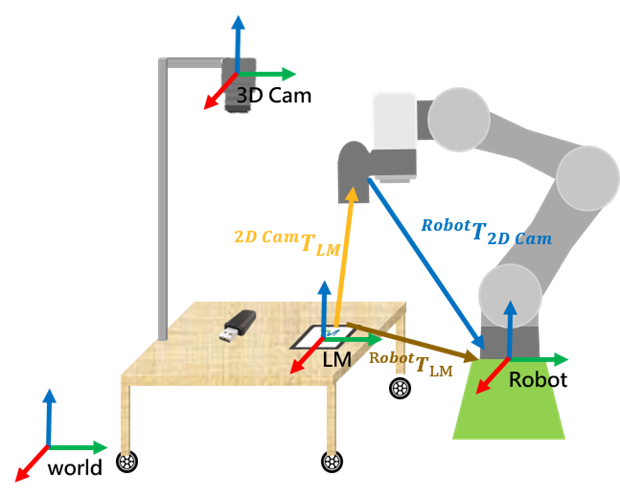
• Place the landmark at a fixed position on the table.
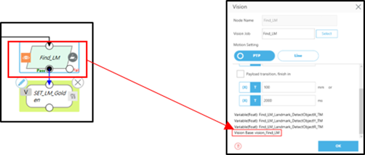
• Then, create a vision job to locate the Landmark and obtain the Landmark’s Vision Base and the variable Base["Vision_Find_LM"].Value. This relationship is denoted as RobotTLM , and the relationship formula is as follows:

- At this point, RobotT3D Cam and RobotTLM are known. To obtain the hand-eye relationship after moving, we must first determine the relationship LMT3D Cam before moving. The relationship LMT3D Cam is as follows:

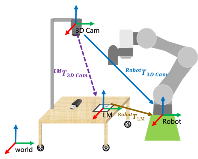
- Next, create the global variable “g_3DCamToLM”
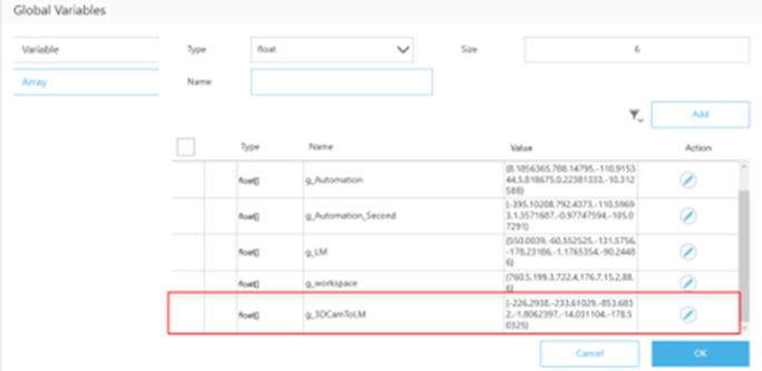
• Use the ‘changeref’ function within the set node to change the description of the 3D Camera Base from Robot Base to Landmark’s Vision Base. This relationship is denoted as LMT3D Cam, representing the pose of the 3D Camera in Landmark’s Vision Base.
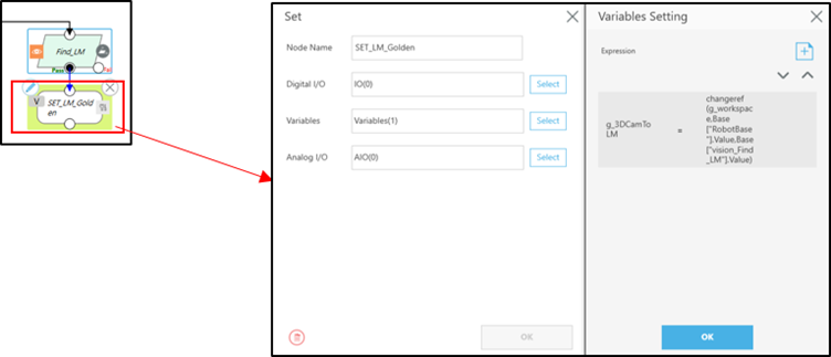
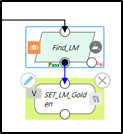
- After executing these two nodes, which are the preparatory steps
- Once the setup is completed, RobotT3D Cam becomes a known value as well.
After Moving - Unfixed Robot Base/Camera
- Base on the settings before moving, the relationship LMT3D Cam is already known. After moving, capture the LM again to obtain the new relationship of LM relative to the Robot RobotT'LM. . Combing RobotT'LM , we can derive the new workspace after moving, which is RobotT'3D Cam . . The relationship is as follows:

- Using the relationship RobotT'3D Cam in combination with 3D CamTworld, we can transform the object in the World Base worldPobject to the new Robot Base, which is RobotP'object . The relationship is as follows:

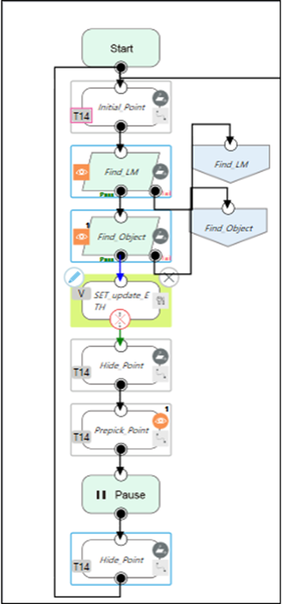
- Set the initial position to a location where is can capture the Landmark
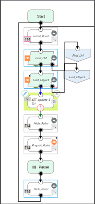
- First, set the Landmark’s vision job before the object’s vision job , as shown in the diagram.
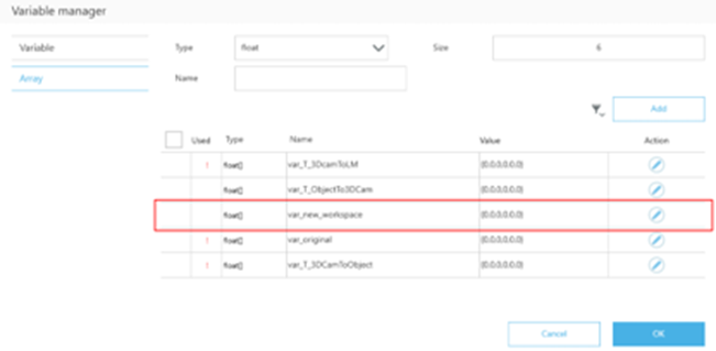
- Add the variable “var_new_workspace” to describe the relationship RobotT'3D Cam
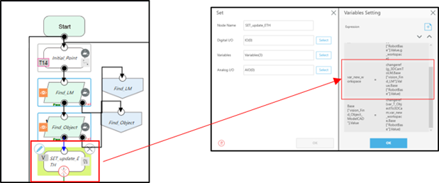
- In the previous ‘Set_update_ETH’ set node, use the ‘changeref’ function to change the pose of the 3D Camera described in landmark’s Vision Base to Robot Base. This action establishes the relationship RobotT'3D Cam,, representing the new Workspace.
• At this point, the relationship RobotT'3D Cam is also known, indicating that we have obtained a new Workspace.
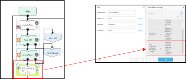
• Next, by combining the new Workspace RobotT'3D Cam with the transformation 3D CamTworld , we deduce the object’s new position in Robot Base RobotP'object , which is the object’s new Vision Base. Similarly, using the ‘changeref’ function, we convert the object’s pose described in the 3D Camera Base to Robot Base, obtaining RobotP'object.
• Finally, record this relationship in the variable ”Base[“Vision_Find_Object_ModelCAD”].value” of the original object’s Vision Base to update the Vision Base accordingly.
Execute the Project
Finally, execute this project. The process flow is shown in the diagram below. The picking point ”Prepick_Point” will be updated according to the movements of the camera or the robot base.
Was this article helpful ?