How to Create a 3D Model Using a Smartphone and Import it into a Virtual Scene
Updated on 2026 / 10 / 20
Examples are valid for:
TMflow Software version: 2.26 or above and TMflow Simulator
TM Robot Hardware version: All
Other specific requirements: None
Note that older or newer software versions may have different results.
Purpose
Explain how to create a 3D model using a smartphone and import it into TMflow.
Consisting of four sections, this article shows how to scan and import a leather car seat:
- Scan the Object Using a Smartphone
- Create Coordinates to Align the Physical and Virtual Scenes (Optional Step)
- Import the Object’s CAD Model File into TMflow Simulator
- Import a Virtual Scene
Procedure
Scan the Object Using a Smartphone
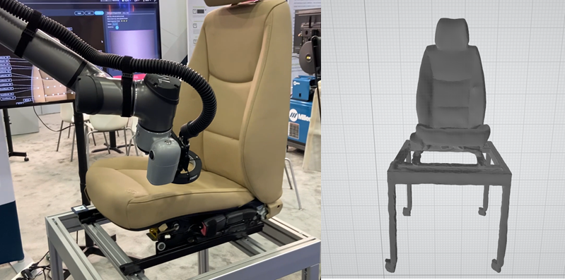
The TMscene system requires the 3D model of the target object. If no model files are available, you can use a smartphone 3D scanning app, such as Scaniverse, Polycam, RealityScan, or Luma AI, to quickly create one. Simply move the smartphone around the target object to generate a corresponding 3D model. Once the scan is complete, export the model in .ply, a format supported by TMscene. The figure below is a leather car seat model created using a smartphone.
 | NOTE: The availability of 3D scanning apps may change over time as new apps are released or existing apps are no longer updated. Before use, check which apps are currently available. For scanning instructions, refer to the documentation for the app of your choice. |
2. Create Coordinates to Align the Physical and Virtual Scenes (Optional Step)
To make it easier to change the position of the scanned model in the virtual scene, you can define the object’s origin in the scanned model’s file. In the figure below, a Landmark is placed near the leather car seat so that the robot can locate the seat during operation.
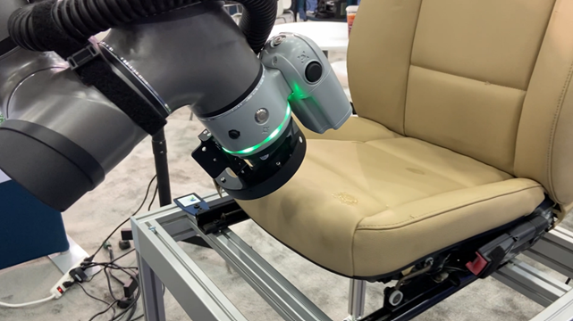
Without completing this step, positioning the object at the corresponding location in the virtual scene can take plenty of time. So, you should change the object’s origin coordinates using its scanned model file. To make such adjustments, use software that supports .ply, such as MeshLab, Blender, or CloudCompare. The following example uses MeshLab.
| NOTE: The availability of software that supports .ply may change over time as new software is released or existing software is no longer updated. Before use, check which software is currently available. For instructions, refer to the documentation for the software of your shoice. |
Open the model file
After MeshLab is installed, open the scanned .ply file.
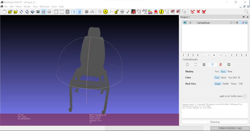
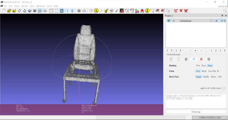
Change the display settings for the model. The grid display is enabled In this example,.
Change the object’s origin coordinates
The coordinates defined in this example is the Landmark coordinates— where the X, Y, and Z axes are marked in red, green, and blue, respectively.
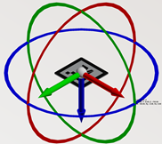
To define the coordinates for the leather car seat model, go to Filters > Normals, Curvatures and Orientation > Transform: Translate, Center, Set Origin in MeshLab to open the settings dialog box. In the dialog box, set Transformation to Set new Origin and select Trackball Center from New Origin.
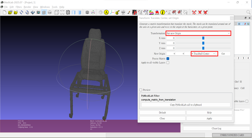
Use the following mouse controls to adjust the view or position the Trackball center:
- Double-click the left mouse button to move the Trackball center to a point on the object’s surface.
- Scroll the mouse wheel to zoom in or out.
- Press and hold the mouse wheel while moving the mouse to pan.
- Press and hold the left mouse button while moving the mouse to rotate the view.
Once the Trackball center is at the desired position, click Get, then Apply, to set the new origin for the object.
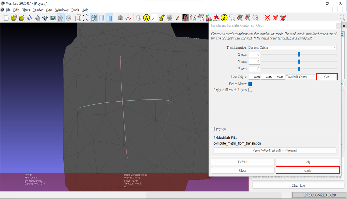
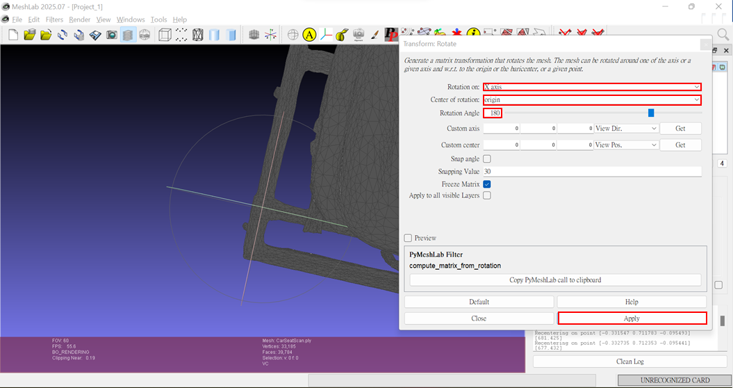
After repositioning the object’s origin, change the orientation of the object's origin coordinates. Go to Filters > Normals, Curvatures and Orientation > Transform: Rotate. In this example, the scanned .ply model only needs 180° rotation around the X-axis. Select X axis from Rotation on and origin from Center of Rotation, then enter 180 in Rotation Angle. Click Apply to apply the change.
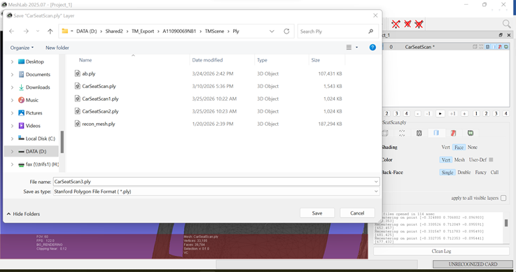
Save the model file
Go to File > Export Mesh As to export the modified model.
3. Import the CAD model file into TMflow Simulator
Create a shared folder or use a USB drive
For instructions on creating a shared folder or using a USB drive, read Section 5.6.2.1 or 5.6.2.4 of Software Manual TMflow_SW2.26 or later version.
This example uses a shared folder to set up a network service.
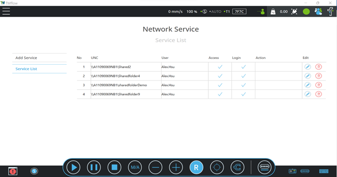
Move the CAD model file to the new folder
The path of the folder used in the example is:
D:\TMsceneDemoFile\sharedfolderDemo (name of shared folder)\TM_Export\A11090069NB1 (device name)\TMScene\Ply
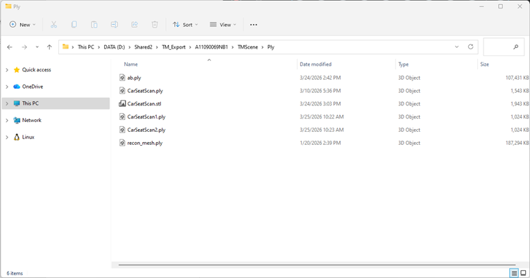
| NOTE: Place the .ply file in a folder with the following path: <name of shared folder or USB device>\TM_Export<device name>\TMScene\Ply |
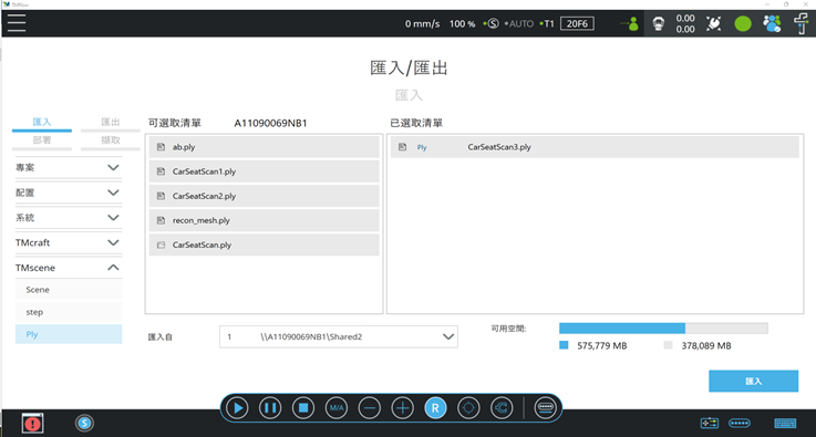
c. Import the CAD model file into TMflow through Import/Export
Click Import > TMscene > Ply in Import/Export to import the CAD model file into TMflow.
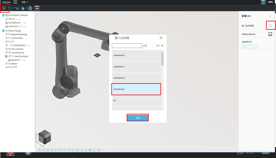
4. Import a Virtual Scene
Add a CAD model to the virtual scene
The selected CAD model appears at the origin of the virtual scene.
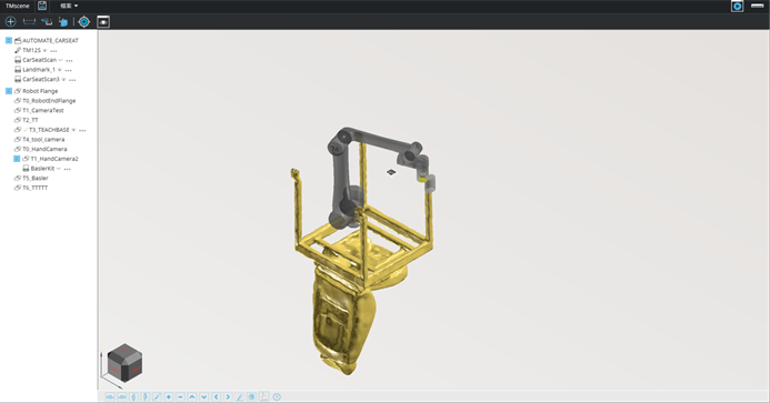
Set up the virtual scene
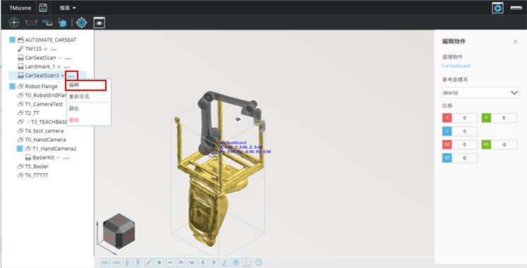
Use the Edit features in an object’s menu to move the object in TMscene. Once opened, the Edit panel appears on the right side of the TMscene window, and a drag control at the object’s origin. You can change the object’s position by dragging it or defining its coordinates in the Edit panel.
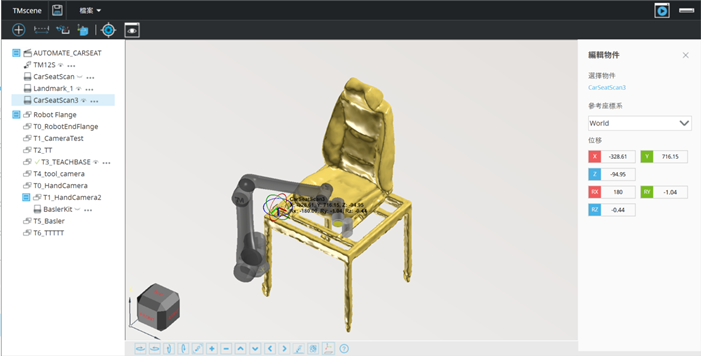
The origin and coordinates of the CAD model shown in the figure below were redefined in Step 2, so the object can be moved by entering its coordinates. Use the Landmark coordinates obtained using the physical robot to place the leather car seat at the corresponding position.
These four steps explain how to create a 3D model using a smartphone, modify the model, import it, and perform initial alignment between the physical and virtual scenes.
| NOTE: The 3D modeling process demonstrated and the repositioning of the model may introduce errors that are not immediately apparent. For precision applications, please carefully check the accuracy of the resulting alignment. |
Was this article helpful ?