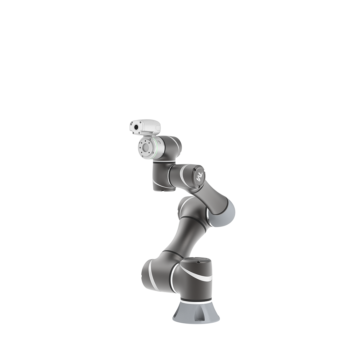
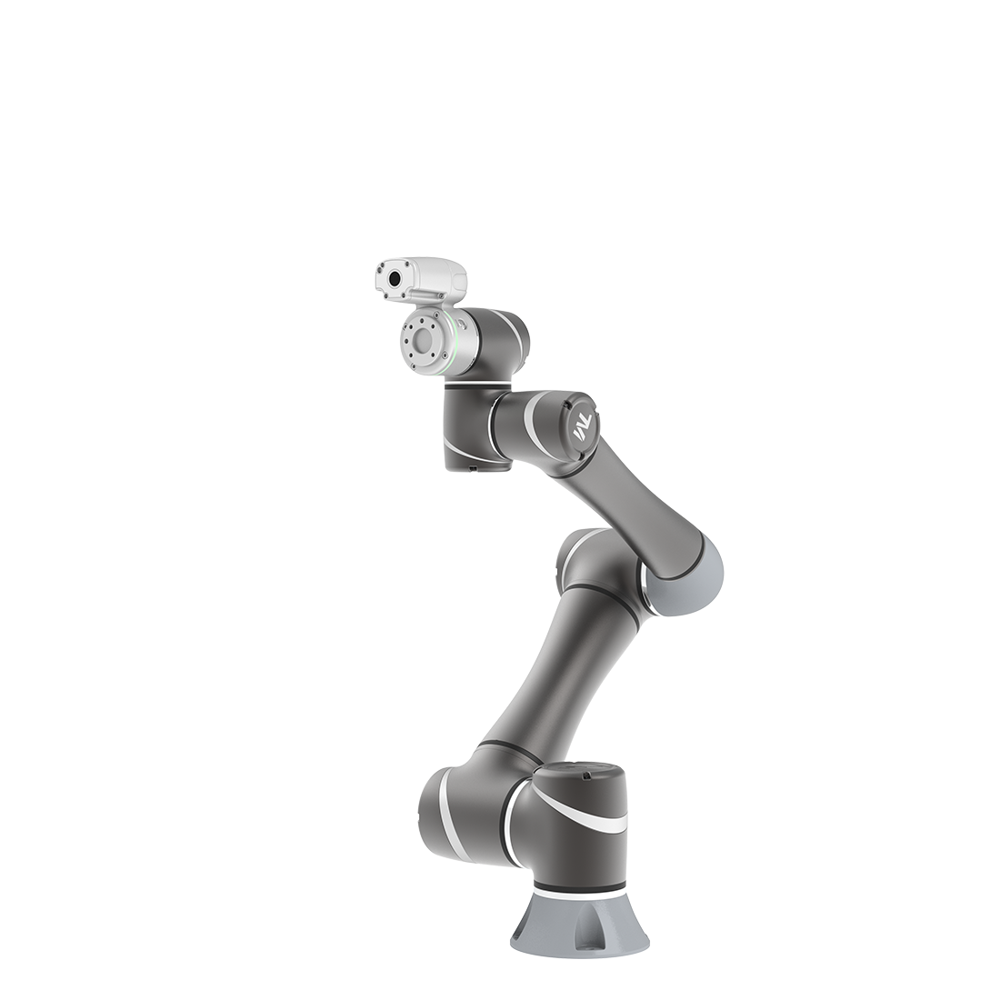
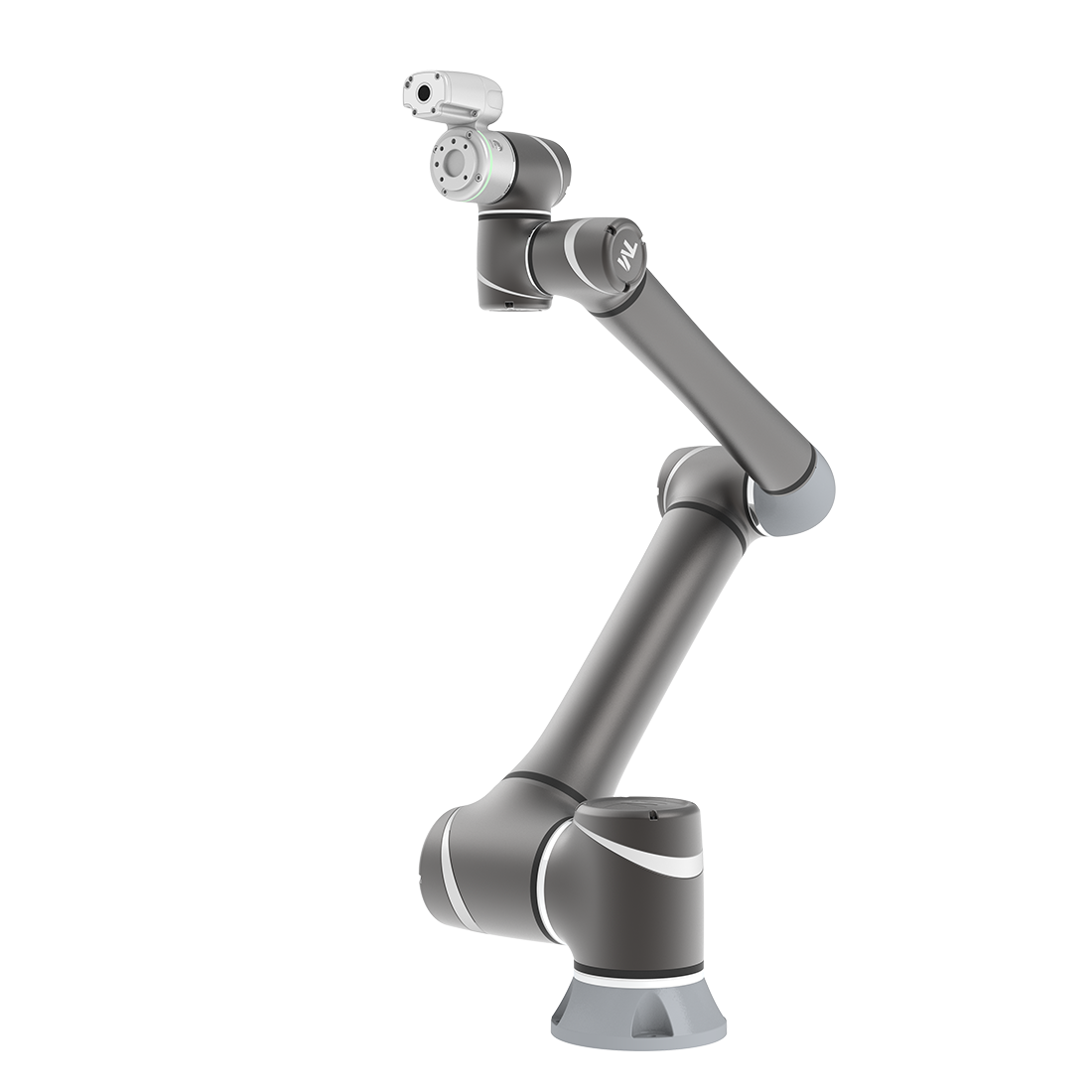
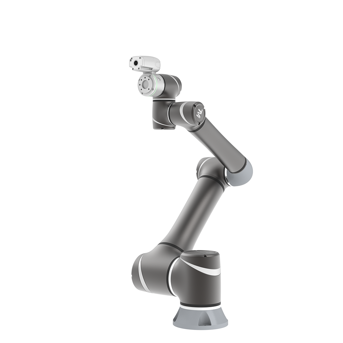
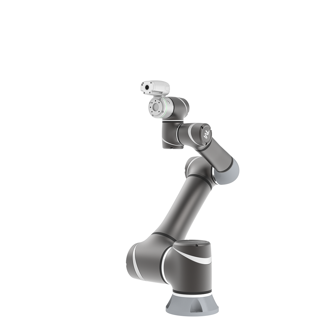
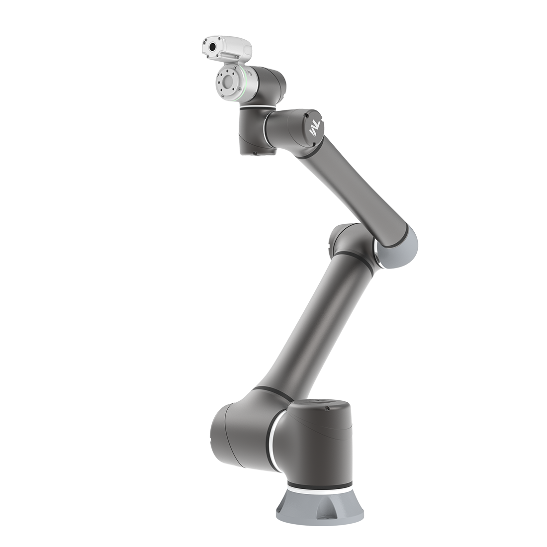
External 2D Camera as EIH Camera Calibration Workflow
Updated on 2026 / 07 / 23
Examples are valid for:
TMflow Software version: 2.22 or above.
TM Robot Hardware version: All
Other specific requirements: None
Note that older or newer software versions may have different results.
Background
The built-in TM Robot camera is a zoom camera suitable for most scenarios. If you have specific requirements for resolution, field of view, working distance, or capture speed, you will need an external camera and must complete intrinsic calibration. When the camera moves with the robot arm, hand-eye calibration is also required to convert image coordinates into robot coordinates.
Camera Intrinsic Calibration
Confirm environment and lens parameters → Adjust camera → Capture 15 calibration board images → Compute intrinsics
1. Confirm environment and lens : Verify working distance (D), field of view (FOV), and depth of field(L). Check pixel size (mm) and focal length (f), then estimate the target aperture using (recommended k = 2).
Excellent sharpness  | Poor sharpness  |
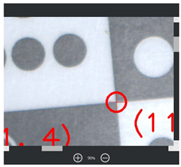 | 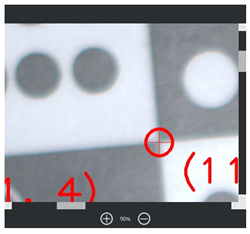 |
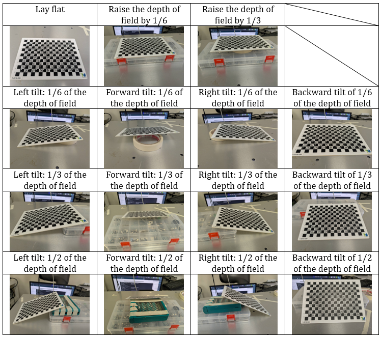
- When tilting the board, keep the entire surface within the depth of field. Keep the board flat and avoid movement at the moment of capture.
- Corner points should cover as much of the image as possible. Use multiple images to complement coverage if one image is insufficient. Only corner points marked in red are included in the calculation.
| Common Mistakes | Recommended Actions |
| Changing aperture, focus, or working distance during calibration | Lock settings after camera adjustment and keep them unchanged |
| Rotating the board only within the same orientation | Change the normal vector direction to ensure sufficient pose diversity |
| Board outside depth of field, bent, or moving during capture | Confirm corner points are sharp; reinforce the board and sedure it before capture |
| Complete corner coverage | 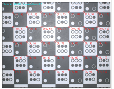 | 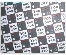 | 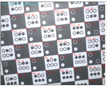 | 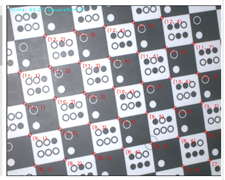 |
| Multiple images collectively covering the FOV | 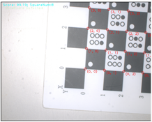 | 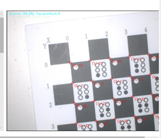 | 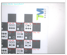 | 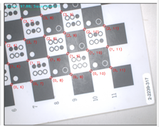 |
| FOV do not overlap | 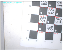 | 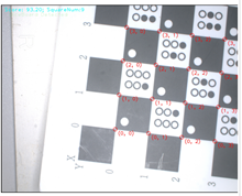 | 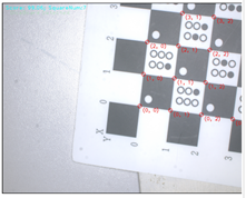 | 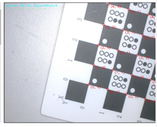 |
Camera Hand-Eye Calbiration
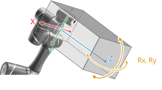
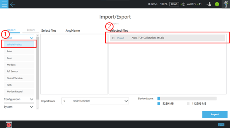
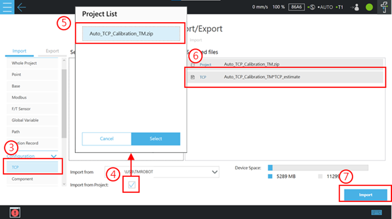
6. Run Calibration : Bind the EIH camera, fix Landmark 2.0 on the actual work plane, set capture points, capture point by point, and confirm that `HandCamera2` is created successfully.
Key Reminders
- Camera mounting position and calibration environment must match the actual application. Aperture, focal length, and working distance must remain the same as in intrinsic calibration.
- Landmark should be centered and occupy about 1/9 of the image, fully within the field of view and clearly visible during capture.
| Common Mistakes | Recommended Actions |
| Loose camera mount or position changed after calibration | Secure installation and do not move the camera after calibration |
| LM out of frame or improper size in image | Center it and keep it at about 1/9 of the image for stable detection |
| Calibration environment differs from actual application | Calibrate at the actual working position and height |
| Wrong Standard / Customized Mode selected | Choose the mode based on measured installation offset |
Was this article helpful ?