Application of Techman PROFINET IO device solution in Simens PLC and software
Updated on 2026 / 08 / 27
Examples are valid for :
TMflow Software version : All versions
TM Robot Hardware version : All versions
Other specific requirements : None
Note that older or newer software versions may have different results.
Overview
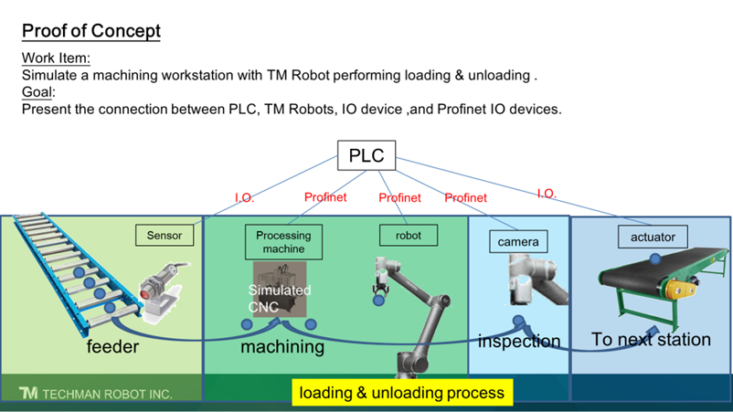
A loading and unloading process will be outlined, utilizing 2 Siemens PLCs and 2 Techman robots.
• PLC 1 acts as a Procedure control, and PLC 2 acts as a CNC machine.
• Robot 1 acts as a Loading/unloading machine, and robot 2 acts as an Inspection station.
There is also a simulated Digital Input (DI) sensor to detect delivered objects
Procedures
- Object is delivered
- The Loading/unloading machine is informed to move objects to the CNC machine for processing
- The object is moved to the CNC machine
- CNC process is initialized
- CNC process is completed
- The object is moved to the Inspection station
- The inspection station informs the loading/unloading machine what patent is assigned to the object
Hardware Configuration
- Techman Robot
- Robot 1
- TM5-900
- Hardware : 3.2
- HMI : 1.81.1200
- Robot 2
- TM5-900
- Hardware : 3.2
- HMI : 1.82.1200 or above
- Robot 1
- PLC
- PLC 1: S7-1200 CPU1214 DC/DC/DC 6ES7 214-1AG40-0XB0
- PLC2: S7-1200 CPU1215 DC/DC/DC 6ES7 215-1AG40-0XB0
- TIA Portal : V15
- 123 number card
TIA V15
Networks
In this application, five devices are used in the network, eg.
- HMI_1
- Master-PLC
- Slave_PLC
- PROFINET IO device 1 (robot1)
- PROFINET IO device 2 (robot2)
Kindly refer to the download sample in the attached file name : PLC_Project_loadingunloadingProcess
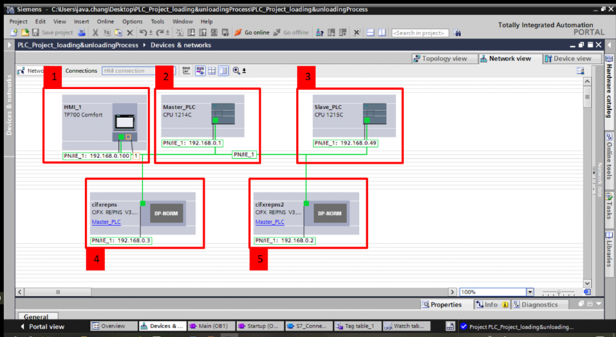
1. HMI_1: Simatic HMI Simulator
2. Master_PLC: Procedure Control
3. Slave_PLC: CNC machine
4. cifxrepns: Loading unloading machine
5. cifxrepns2: Inspection station
Building Tag Table
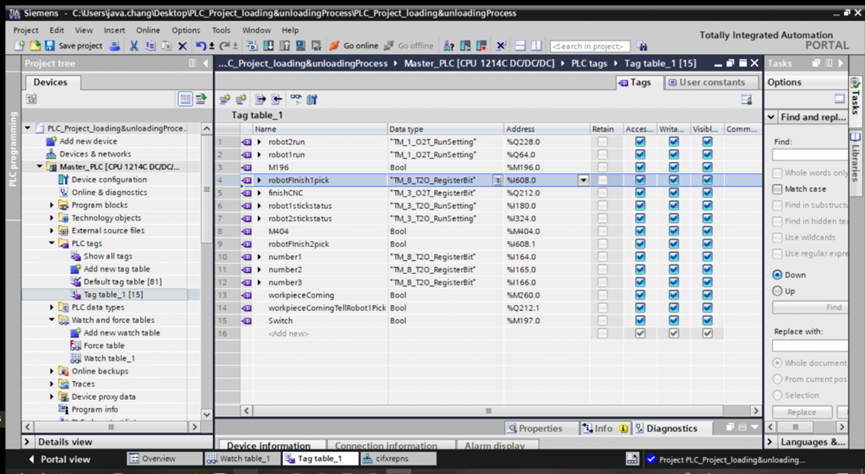
“I” refers to input, which means process state
“Q” refers to output, which means process control
“M” refers to memory, which is an auxiliary tag for saving values in the memory byte area
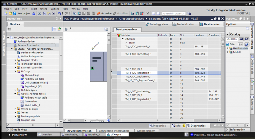
The tag's address should correspond to the device modules. For example, the tag name “robotFinish1pick” corresponds to robot1 “TM_8_T2O_RegisterBit”.
Program Block
Master_PLC[OB1] :
Network 1: Starting the connection with Slave_PLC
Network 2: Turning on robot 1
Network 3: Turning on robot 2
Network 4: M260 is a sensor that detects the arrival of a workpiece. If M260 receives the signal, robot 1 will be notified due to Q212.
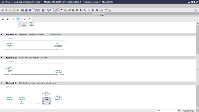
Network 5: If Robot1 finishes picking up the workpiece, it will inform CNC (Slave_PLC) to start working.
Network 6: CNC finishes working and commands robot 1 to pick up the workpiece.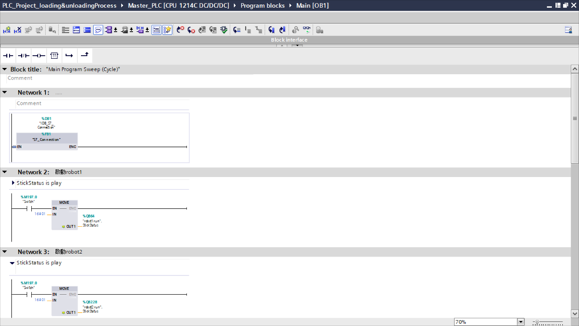
2. Slave_PLC :
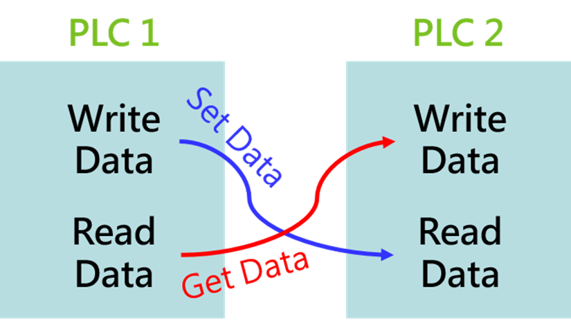
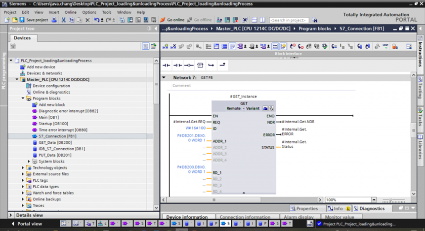
Briefly introduce the communication mode between two PLCs. Each PLC has two areas: write data area and read data area. PLC 1 set data from the write data area to the read data area of PLC2 and get data from the read data area to the write data area of PLC 2.
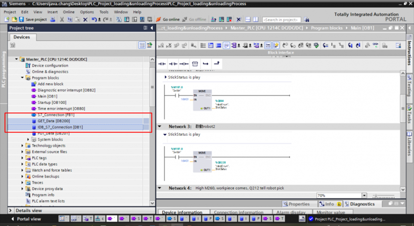
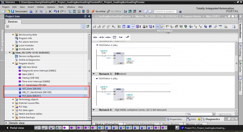
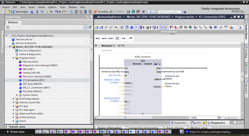
Created a function block in PLC1, and operate data exchange here.
TMflow Project
Please refer to the file attached name : TMflow-Project
Was this article helpful ?